
Wheel, Tire & Vehicle Dimension Testing Equipment
Automatic tire tread depth measuring instrument | CTLT-3/CTLT-15
A manual tire tread depth tester creates significant bottlenecks in high-throughput vehicle testing lanes. Inconsistent gauge positioning, transcription errors, and inspector fatigue compromise test consistency and lane...


A manual tire tread depth tester creates significant bottlenecks in high-throughput vehicle testing lanes. Inconsistent gauge positioning, transcription errors, and inspector fatigue compromise test consistency and lane efficiency. Transitioning to a drive-over tire tread depth measuring instrument resolves these operational delays by capturing full-width groove wear data automatically as vehicles pass through the inspection station.
Cartesykj engineers heavy-duty automotive safety inspection equipment and complete vehicle inspection line solutions. The CTLT series uses line laser measurement technology to evaluate groove depths, identify tread wear patterns, and inspect axle consistency without manual wheel removal. This technical guide outlines the verified engineering specifications, operational principles, load ratings, and installation criteria for the CTLT-3, CTLT-3F, CTLT-15, and CTLT-15F tire tread depth measuring instrument product family.
Table of Contents:
- Equipment Definition and Material/Application Scope
- Buyer Value and Sourcing Considerations Supported by Facts
- Technology Working Principles and System Classifications
- Documented Materials, Quality Controls, and Specifications
- Practical Sourcing and Risk-Mitigation Guidance
- Frequently Asked Questions
- Engineering Consultation and Specifications
Equipment Definition and Material/Application Scope
The Cartesykj CTLT platform is an automated tire tread depth measuring instrument engineered for modern vehicle inspection stations. Operating as drive-over vehicle tire inspection equipment, the system uses non contact tire tread measurement methods to scan rolling tires directly on the test lane. High-speed line lasers project onto the tire surface while visual sensors capture reflected light paths, compiling full tread elevation profiles within approximately 20 seconds under standard operating procedures.
As an integrated tire tread depth scanner, each unit performs automatic tire tread depth measurement across a defined 0–25 mm depth range. The underlying tire tread depth detection system eliminates mechanical probes, enabling operators to measure tread depths across passenger cars, commercial transport vehicles, transit buses, and heavy-duty freight trucks without removing wheels.
Primary Inspection Capabilities
- Automatic Tire Tread Depth Measurement: Line laser technology measures groove depths across a verified 0–25 mm measurement range with 0.01 mm stated accuracy.
- Tire Wear Analysis: Proprietary software processes transverse elevation profiles to conduct automated tire tread wear measurement across ribs and shoulders.
- Intelligent Tire Condition Alerts: The system automatically flags shallow depths, severe groove loss, and abnormal tire conditions.
- Automatic Inspection Reports: Workstations generate printable inspection reports and summary files immediately following wheel roll-over.
- Tire Replacement Reminders: The tire wear detection system delivers automated replacement reminders based on configurable wear parameters.
- Same-Axle Tire Consistency Inspection: Evaluates tire model, specification, and tread pattern consistency across tires mounted on a shared axle.
- Tire Specification Inspection: Captures tire specification parameters, tread surface condition, and visible sidewall features.
- Retreaded Tire Alerts: Generates automated alerts for detected retreaded tires on specific vehicle categories, including highway buses, tourist buses, and school buses.
- Inspection Data Integration: Synchronizes scan records with vehicle inspection station equipment management databases using compatible communication protocols.
- Customizable Inspection Reporting: Configures data structures and export uploads according to project and statutory authority standards.
Material and Application Scope
The CTLT series is deployed across municipal safety inspection centers and industrial fleet facilities requiring dependable vehicle safety inspection equipment. Primary application environments include:
- Statutory vehicle inspection station equipment lines.
- Commercial fleet maintenance facilities conducting commercial vehicle tire inspection.
- Freight logistics hubs requiring heavy vehicle tire inspection equipment.
- Passenger car diagnostic bays demanding high-speed automatic tire wear inspection.
- Municipal public transit depots performing heavy vehicle and bus tire safety checks.
- Turnkey automatic vehicle inspection system projects requiring synchronized lane automation.
Buyer Value and Sourcing Considerations Supported by Facts
Procuring a tire tread depth measuring instrument requires aligning mechanical ratings with daily operational traffic. Traditional manual tire depth gauges create severe operational constraints: technicians must walk into active lanes, manually position gauges, and log values by hand. Optical laser tire tread depth measurement automates data logging, eliminates operator exposure to moving vehicles, and delivers consistent results across high-volume test bays.
The CTLT tire tread depth measuring instrument product line is divided into two primary single axle load ratings and two civil installation formats:
Model
Installation Format
Max Single Axle Load
Tire Width Specification
Depth Measurement Range
Stated Accuracy
Power Supply
CTLT-3
Ground-mounted
3,000 kg
350 mm
0–25 mm
0.01 mm
220V
CTLT-3F
Foundation-mounted
3,000 kg
350 mm
0–25 mm
0.01 mm
220V
CTLT-15
Ground-mounted
15,000 kg
350 mm
0–25 mm
0.01 mm
220V
CTLT-15F
Foundation-mounted
15,000 kg
350 mm
0–25 mm
0.01 mm
220V
Note: The technical documentation defines 350 mm for the tire width specification without listing a minimum-to-maximum range. Buyers should verify regional oversized tire widths with engineering teams prior to procurement.
Axle Load Sourcing Parameters
Selecting the correct single axle load capacity protects the mechanical structural integrity of your tire tread depth measuring instrument. Underspecifying load capacity risks permanent frame distortion, laser optical misalignment, and sensor failure under heavy vehicles. Operations teams must assess regional fleet compositions before specifying equipment models.
The CTLT-3 and CTLT-3F provide a maximum single axle load of 3,000 kg, tailored for passenger cars, light delivery vans, and small utilities. For truck tire tread depth inspection, municipal buses, and multi-axle freight trailers, the CTLT-15 and CTLT-15F deliver an expanded maximum single axle load of 15,000 kg. Sourcing the appropriate model ensures reliable drive over tire tread depth measurement across all target vehicle categories.
Technology Working Principles and System Classifications
The CTLT tire tread depth measuring instrument functions as an optical profiler and tire tread scanner. Understanding its working principle helps test engineers maintain proper alignment and throughput in automated testing bays.
Working Principle and Optical Triangulation
When a vehicle passes over the scanning platform, line laser projectors cast uniform optical lines across the tire contact surface. Calibrated optical sensors record surface reflections at high frame rates. Because groove voids displace the projected laser lines relative to the raised tread ribs, processing algorithms calculate groove depths using geometric triangulation across a 0–25 mm measurement range.
This continuous line projection enables comprehensive automatic tire tread inspection. Rather than capturing isolated spots, the laser profiler records groove depths, transverse wear profiles, and shoulder drop-offs across the contact area, ensuring thorough automotive testing equipment evaluations.
Drive-Over Inspection Workflow
- Lane Approach: The vehicle drives onto the testing platform at a steady walking speed without stopping.
- Laser Data Collection: Line lasers sweep the rolling tread face, capturing continuous elevation profiles.
- Signal Processing: The industrial computer processes sensor data, isolating tread ribs, wear indicators, and circumferential grooves.
- Wear Analysis: The software analyzes tread wear patterns, cross-references same-axle specifications, and verifies depth compliance.
- Report Generation: The system compiles and delivers complete measurement reports within approximately 20 seconds.
System Classifications: Ground-Mounted vs. Foundation-Mounted
Cartesykj configures each tire tread depth measuring instrument into two physical mounting styles to suit different station layouts.
Ground-Mounted Platforms (CTLT-3 and CTLT-15): These units bolt directly onto existing reinforced concrete bay floors. Vehicles roll over the scanning assembly via shallow approach and exit ramps. This configuration eliminates deep concrete excavation, making it suitable for leased facilities or test bays where cutting foundation pits is impractical.
Foundation-Mounted Platforms (CTLT-3F and CTLT-15F): Foundation-mounted models install flush into pre-cast concrete pits. The top plate aligns with the workshop floor, eliminating ramp transitions. This layout provides smooth vehicle transit, minimizes approach shudder, and integrates seamlessly into multi-equipment vehicle inspection line layouts alongside brake testers, side slip testers, and axle load testers.
Documented Materials, Quality Controls, and Specifications
High-volume inspection lanes subject testing platforms to continuous cyclic loading, vibration, and dynamic braking forces. The CTLT tire tread depth measuring instrument incorporates an integrated welded structure engineered to maintain frame stability under dynamic axle passes up to 15,000 kg.
Structural Construction
The integrated welded structure provides mechanical rigidity to preserve optical alignment between line laser emitters and sensor receivers. Frame deflection under heavy commercial vehicles would skew triangulation angles and invalidate stated accuracy. Protective optical windows shield internal laser modules and visual cameras from falling road debris, grit, and moisture.
Operational teams must incorporate periodic window cleaning into station protocols. Accumulations of road mud, gravel, or standing water on the protective glass interfere with laser transmission and visual data capture.
Electrical and Power Specifications
All CTLT models operate on a standard 220V power supply. This eliminates the necessity of running 380V industrial three-phase drops to the tire testing bay, simplifying retrofit integration into existing vehicle inspection stations. Internal power regulation units condition incoming power to maintain stable voltage for line laser modules and computer processing hardware.
Software Capabilities and System Integration
The accompanying software package transforms raw optical datasets into structured inspection records. Key software functions of the tire tread depth measuring instrument include:
- Automatic tire tread depth measurement across a 0–25 mm depth range.
- Profile calculation resolving to a manufacturer-stated 0.01 mm accuracy.
- Wear imbalance alerts highlighting abnormal tire conditions, uneven shoulder wear, and inflation discrepancies.
- Tire replacement reminders triggered by user-defined threshold limits.
- Consistency checks verifying matching tire models, specifications, and tread patterns on shared axles.
- Retreaded tire inspection alerts configured for highway, tourist, and school buses.
- Customizable inspection reporting and data upload via compatible network communication protocols.
Practical Sourcing and Risk-Mitigation Guidance
Procuring a commercial tire tread depth measuring instrument requires careful evaluation of station throughput, vehicle demographics, civil limitations, and network architecture. Buyers can use the following procurement framework to guide equipment selection.
Procurement Selection Checklist
- Determine Vehicle Demographics: Audit target inspection lanes. For light passenger cars, select the CTLT-3 or CTLT-3F (3,000 kg maximum single axle load). For commercial fleets, transit buses, and freight trucks, specify the CTLT-15 or CTLT-15F (15,000 kg maximum single axle load).
- Evaluate Civil Engineering Options: Assess floor excavation limits. If pit cutting is prohibited by lease terms, source ground-mounted CTLT-3 or CTLT-15 units with ramps. If flush installation is preferred for smooth lane transit, prepare civil pits for foundation-mounted CTLT-3F or CTLT-15F models.
- Verify Tire Dimensions: The manufacturer specification defines a 350 mm tire width parameter. Confirm that local vehicle tire widths match platform scanner widths before placing equipment orders.
- Review Software Integration: Verify that local station management systems support compatible communication protocols to receive automated measurement data and customizable report uploads.
- Establish Maintenance Protocols: Maintain optical window cleanliness. Station operating procedures should include daily optical window wipe-downs to ensure uninterrupted measurement accuracy.
Operational Comparison: Manual Gauges vs. Automatic CTLT System
Operational Parameter
Manual Tire Tread Tester
CTLT Tire Tread Depth Measurement System
Inspection Speed
3–6 minutes per vehicle
Approximately 20 seconds
Measurement Method
Manual contact pin at spot locations
Non-contact line laser surface scan
Data Transcription
Manual technician logging
Automated digital report generation
Operator Safety
Inspector works in active traffic lane
Drive-over scan inside vehicle lane
Axle Consistency Check
Manual visual review
Automated same-axle consistency inspection
Measurement Range
Varies by mechanical gauge
0–25 mm depth range (0.01 mm accuracy)
Implementing an automated tire tread depth measuring instrument removes human measurement bias, improves lane throughput, and provides verifiable inspection records for statutory compliance programs.
Frequently Asked Questions
What is an automatic tire tread depth measuring instrument?
An automatic tire tread depth measuring instrument is drive-over vehicle safety inspection equipment that uses non-contact line laser technology to measure tire tread depth, analyze wear conditions, and generate inspection reports without removing vehicle wheels.
How does automatic tire tread depth measurement work?
As a vehicle drives across the platform, line lasers project onto the tire tread. Visual sensors capture light reflections, and the software calculates groove depths across a 0–25 mm measurement range using optical triangulation, producing inspection data in approximately 20 seconds.
Can Cartesykj equipment inspect commercial truck tires?
Yes. The CTLT-15 and CTLT-15F models feature a 15,000 kg maximum single axle load capacity, engineered specifically for truck tire tread depth inspection, municipal buses, and heavy commercial vehicles.
What is the difference between CTLT-3 and CTLT-15?
The CTLT-3 supports a maximum single axle load of 3,000 kg for passenger vehicles, whereas the CTLT-15 supports up to 15,000 kg single axle load for commercial trucks and heavy vehicles.
What is the difference between CTLT-3 and CTLT-3F?
The CTLT-3 is a ground-mounted unit installed directly on the workshop floor using approach ramps. The CTLT-3F is a foundation-mounted unit installed flush into a concrete pit.
Can the equipment connect with vehicle inspection management software?
Yes. Measurement data can be synchronized with customer management systems where compatible communication protocols are available, supporting customizable inspection report uploads.
Engineering Consultation and Specifications
Selecting the optimal tire tread depth measuring instrument depends on matching your test lane's single axle load demands, civil construction limits, and data management architecture. Featuring an integrated welded structure, 220V power supply, 0.01 mm stated measurement accuracy, and a 0–25 mm tread depth range, the Cartesykj CTLT series provides dependable automation for modern vehicle inspection stations.
Contact our technical engineering team to review foundation requirements, confirm axle load specifications, discuss customizable report configurations, and request detailed quotations for your vehicle testing facility.
Related Products
Compare related inspection systems
Wheel, Tire & Vehicle Dimension Testing Equipment
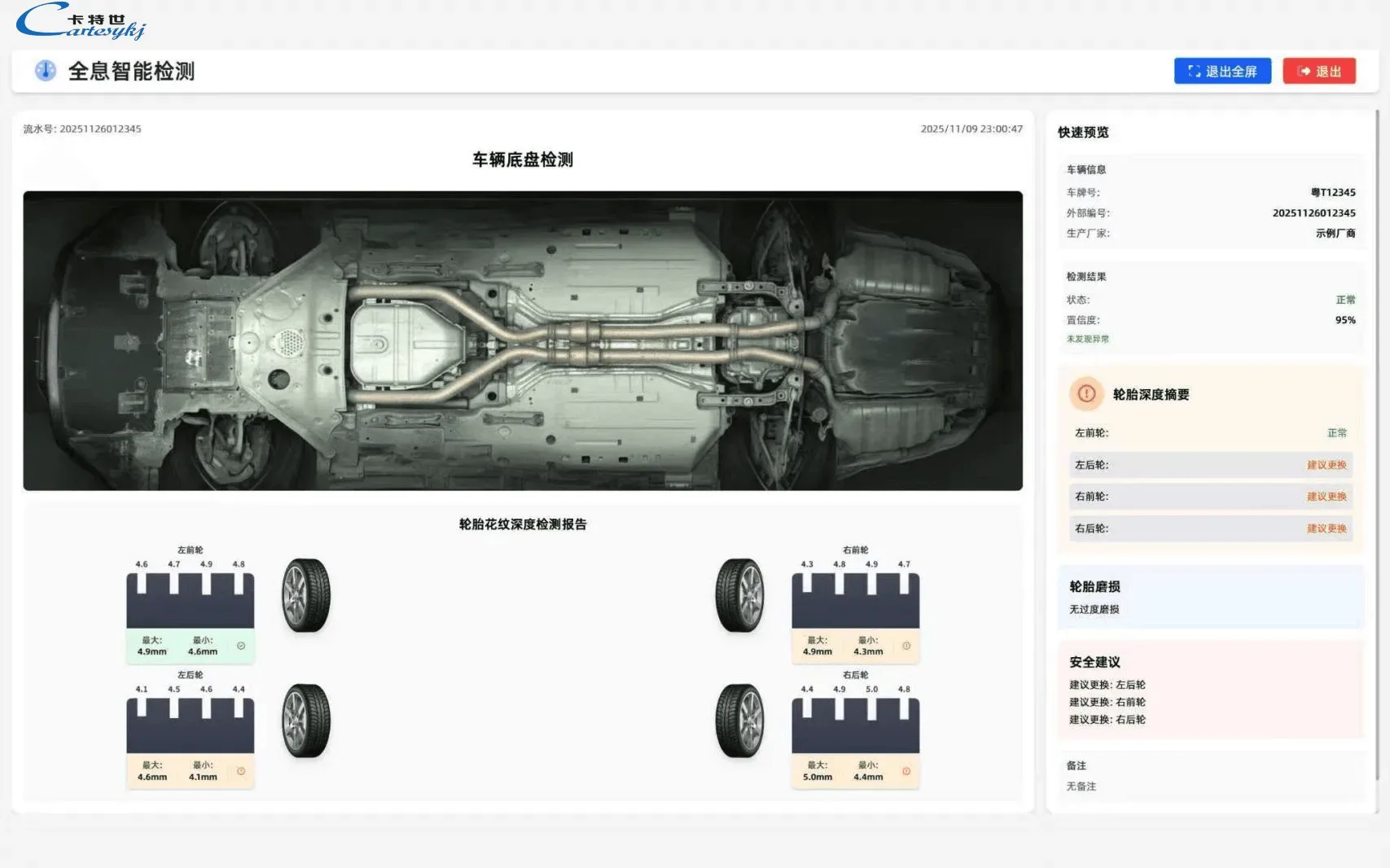
DeepVision:Tire tread Depth & Chassis Holographic Intelligent tester |
View Product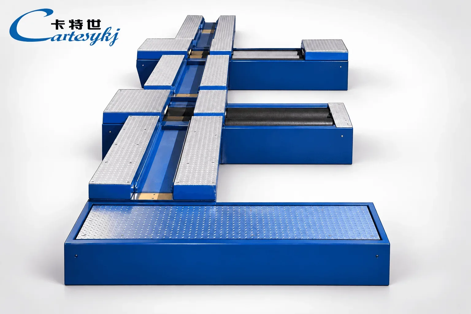
Wheel, Tire & Vehicle Dimension Testing Equipment
Motorcycle (EV) tester for two wheels | CTJZMT-300B
View ProductRequest a Quote
Request configuration and pricing for your project.
Share your vehicle type, inspection lane layout, target capacity, and required model configuration for Automatic tire tread depth measuring instrument | CTLT-3/CTLT-15.
Share the project location, vehicle types, inspection scope, applicable standards, target throughput, site conditions and current stage. We will confirm the configuration scope before discussing pricing.