
Mobile Test Station Equipment
Light and Heavy-Duty Vehicle Inspection Line: CTYJ-10 Mobile Test Station for Cars and Trucks
The CTYJ-10 Light and Heavy-Duty Vehicle Inspection Line combines roller brake testing, side-slip testing, speedometer testing, and axle or wheel-load testing in a mobile station for cars and trucks. Its standard
The CTYJ-10 Light and Heavy-Duty Vehicle Inspection Line combines roller brake testing, side-slip testing, speedometer testing, and axle or wheel-load testing in a mobile station for cars and trucks. Its standard configuration also includes control hardware and software, an LED display for test instructions and results, and supporting equipment for station operation.
The stated maximum axle load is 10,000 kg, and the applicable wheelbase is less than 6,000 mm. These limits need to be matched to the intended vehicles. The axle-load figure should not be treated as a maximum total vehicle weight or as proof that every truck configuration is supported.
For inspection-station operators, the CTYJ-10 provides a defined starting configuration. The project can then add optional inspection equipment and establish the transport, site, electrical, and reporting arrangements required for the planned operation.
Standard Inspection Functions and Optional Equipment
The product information separates the standard inspection modules from equipment available as optional, made-to-order additions.
| Equipment | Configuration status |
|---|---|
| Roller brake tester | Standard |
| Vehicle Sideslip Tester | Standard |
| Vehicle Speedometer Tester | Standard |
| Vehicle Axle (wheel) Load Tester | Standard |
| Suspension tester | Optional |
| Opacimeter | Optional |
| Headlight tester | Optional |
| Emissions testers | Optional |
| Sound-level meter | Optional |
| 30 kVA power generator | Optional |
These classifications follow the supplied CTYJ-10 specification.
Speedometer testing is part of the standard inspection scope. Suspension, headlight, opacity, emissions, and sound-level testing need to be selected separately when required by the project.
The generator also remains an option, even when a generator appears in a product illustration. The quotation and equipment schedule should identify whether it is included in the particular station being supplied.
Separating these items makes proposals easier to compare. Each proposal should state the inspection functions included in its price, the selected options, and any equipment required to operate those functions at the intended location.
Vehicle Capacity and Wheelbase Limits
The supplied technical information identifies the following specifications for the mobile station body:
| Parameter | Stated specification |
|---|---|
| Model | CTYJ-10 |
| Intended vehicle categories | Cars and trucks |
| Maximum axle load | 10,000 kg |
| Applicable wheelbase | <6,000 mm |
| Listed power supply | 380/220 V; connection arrangement requires confirmation |
The wheelbase condition is a strict less-than limit. It should not be rewritten as an inclusive “up to 6,000 mm” specification.
Axle load and total vehicle weight describe different conditions. A vehicle’s total weight alone is therefore insufficient for checking compatibility with this line. The proposed vehicle list should include the axle-loading conditions and dimensions relevant to the manufacturer’s operating limits.
The stated axle-load capacity also does not define the load tester’s measurement range or accuracy. Those are separate instrument specifications that should be provided for the quoted configuration.
Likewise, the label Vehicle Axle (wheel) Load Tester does not establish whether the software reports individual-wheel readings, axle totals, or both. The supplier should identify the actual measurement arrangement and available results.
For a mixed fleet, vehicle compatibility should be documented against the intended cars and trucks, including any axle arrangement, tire, or drivetrain conditions that affect the applicable test procedure.
How the Mobile Vehicle Inspection Line Is Controlled
The standard configuration includes hardware and software for automatic control. An LED display is specified for showing test-process commands, test messages, and results. A printer is also listed among the supplied equipment.
These components provide the described control and information-display arrangement for the Mobile Vehicle Inspection Line. The project documentation should explain the operator’s tasks, how each test is selected or initiated, and how the system identifies completed and incomplete measurements.
Automatic control should be defined through the actual operating sequence. The equipment list does not specify which stages require operator intervention or which assessment decisions are performed by software.
A representative report should show the available results for braking, side slip, speedometer testing, and load measurement. If optional instruments are included, their reporting arrangements should also be demonstrated.
The report review should establish how the system identifies the vehicle, presents measurement units, and applies any agreed evaluation criteria. This connects the supplied controls and reporting equipment to the station’s intended inspection workflow.
Supporting Equipment in the Standard Configuration
The standard list extends beyond the testing instruments. It includes an auxiliary frame, an air compressor, an air-conditioned room, voltage-stabilizing equipment, UPS equipment, and photoelectric switches. A hydraulically controlled lifting mechanism is also listed.
These components should be identified in the final equipment schedule, together with their model-specific specifications and functions.
The hydraulic mechanism requires a clear description of what it moves and its rated capacity. Its presence should not be interpreted as a confirmed vehicle-lifting function or an automatic station-deployment system without that documentation.
The voltage-stabilizing and UPS equipment also need defined operating scopes. The supplier should identify the connected circuits, the equipment supported during a power interruption, and any stated backup duration.
The inclusion of an air compressor does not establish the pneumatic requirements of every optional instrument. Those requirements should be checked against the complete configuration selected for the project.
Electrical Supply and the Optional Generator
The source lists the station’s power supply as 380/220 V, but it does not explain the connection arrangement, phase, frequency, or total electrical demand.
For a U.S. installation, obtain a supply specification for the exact station configuration. It should identify the required connections and the electrical requirements of both the standard equipment and selected options.
The optional generator is listed at 30 kVA. Its suitability should be checked against the station’s actual connected loads, operating sequence, and required supply characteristics. That rating should remain expressed in kVA; it should not be converted into a claim of 30 kW output.
The generator and UPS should also retain separate definitions in the project documents. Their inclusion does not establish a particular whole-station operating duration or confirm that every module can run simultaneously.
Planning Mobile Deployment
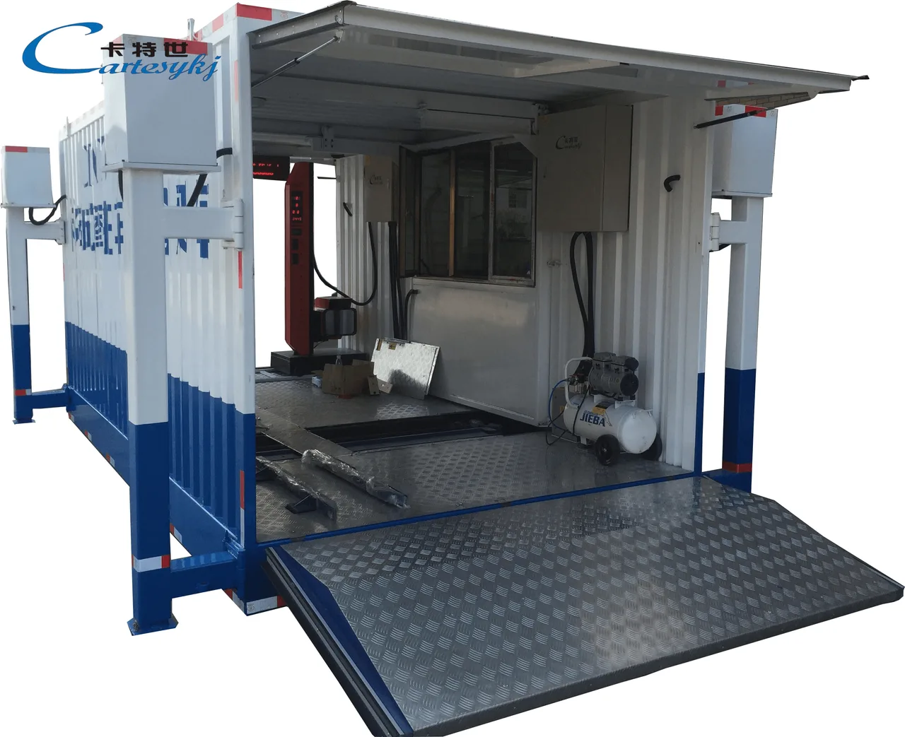
The CTYJ-10 is presented as a mobile testing arrangement with a station body, inspection equipment, access structures, and an operating area. The illustrations show the equipment in deployed and transport-related arrangements.
For deployment planning, request drawings that identify the complete operating footprint and transport dimensions of the selected configuration. Dimensions shown for an individual enclosure or folded component should not be assumed to represent the entire station.
The site plan should account for vehicle approach and departure, testing positions, operator access, supporting-surface requirements, equipment securing arrangements, and utility connections.
The transport method should also be stated explicitly, including whether a carrier is supplied and which handling equipment is needed to position the station. A mobile designation does not, by itself, define the complete transport package.
Where the station will operate at several locations, each proposed site should be assessed against the same manufacturer-defined installation requirements. This provides a consistent basis for planning deployment without assuming a particular setup time or testing throughput.
Integrating Results with Station Operations
When this automotive testing equipment forms part of an existing inspection operation, the required data workflow should be included in the project scope.
The product description mentions network communication, but it does not identify a particular protocol, database connection, or external reporting interface. Any required integration needs its own technical definition and acceptance demonstration.
The station should agree on the information to be transferred, how vehicle records are identified, and how incomplete or repeated tests are handled. A representative inspection record can then be used to check that the supplied system produces the required information.
This review should cover the selected configuration as a whole, including any optional instruments whose results need to appear in the station’s records.
Specify the CTYJ-10 Around Your Vehicle Fleet
Provide your Vehicle Inspection Equipment Manufacturer with the intended vehicle list, axle-loading conditions, wheelbases, testing locations, available utilities, and required inspection functions.
Request a proposal that identifies the CTYJ-10 standard configuration, selected options, confirmed vehicle compatibility, electrical requirements, transport arrangements, and reporting scope. Include an equipment schedule, installation drawings, and a sample report in the technical review.
With those details documented, the station operator can assess the Light and Heavy-Duty Vehicle Inspection Line against the cars, trucks, locations, and inspection procedures it is intended to serve.
Related Products
Compare related inspection systems
Mobile Test Station Equipment
Mobile Test Station for Motorcycles: A Motor Vehicle Inspection System | CTMYJ-750B/CTMYJ-300B
View Product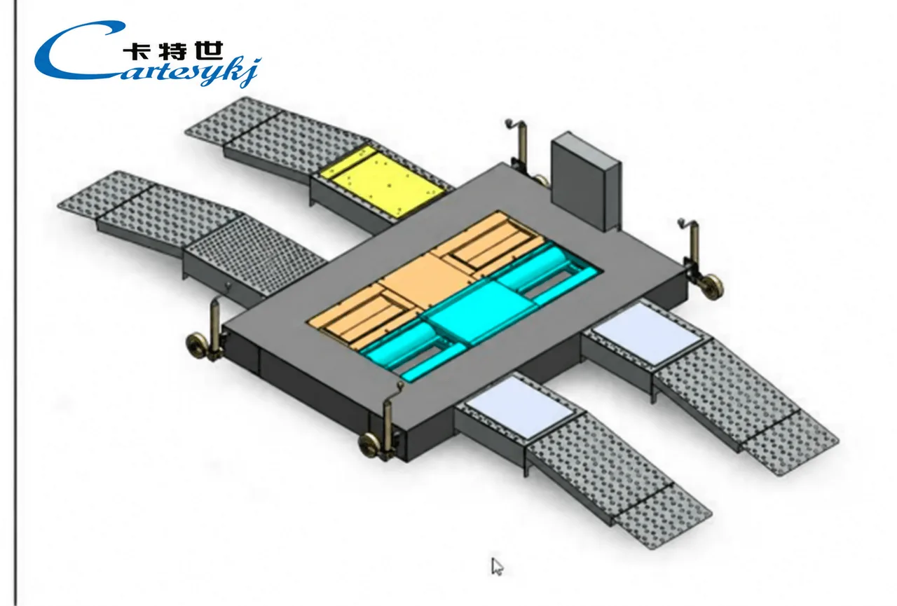
Mobile Test Station Equipment
Mobile Vehicle Inspection Line: Mobile Test Station for Cars | CTMBGT-3-4P
View ProductRequest a Quote
Request configuration and pricing for your project.
Share your vehicle type, operating requirements, and required configuration for Light and Heavy-Duty Vehicle Inspection Line: CTYJ-10 Mobile Test Station for Cars and Trucks.
Share the project location, vehicle types, inspection scope, applicable standards, target throughput, site conditions and current stage. We will confirm the configuration scope before discussing pricing.