
Electric Vehicle Testing Equipment
New Energy Vehicle Safety Inspection Equipment for Charging Safety Testing | EVTE-123-S-A-CTEV-3
New Energy Vehicle Safety Inspection Equipment for charging safety brings together charging-port electrical checks and battery-condition assessment during charging. The cabinet-based system described in the product
New Energy Vehicle Safety Inspection Equipment for charging safety brings together charging-port electrical checks and battery-condition assessment during charging. The cabinet-based system described in the product information uses a host computer and dedicated testing software to manage the inspection process. Its documented functions include charging-port insulation-resistance tests and the collection of charging and battery-status parameters for evaluation.
For an inspection station, these functions provide a defined scope for examining electrical conditions associated with vehicle charging. The usefulness of the results depends on the supported vehicle interfaces, the measurement procedures, and the criteria used to interpret the recorded data.
A charging safety inspection solution should make those relationships clear: what the equipment checks, what information it collects, and what conclusions the resulting report can support.
What Does the Charging Safety Inspection Cover?
The product description lists electrical inspections at both fast- and slow-charging ports, additional checks described as “potential balance” and “voltage balance,” and battery assessment using data obtained during charging. These functions should be defined individually in the equipment specification and inspection report.
| Inspection area | Function listed in the product information | Information needed to interpret the result |
|---|---|---|
| Fast-charging port | Insulation-resistance test | Supported vehicle connections, measurement conditions, reporting units, and evaluation criteria |
| Slow-charging port | Insulation-resistance test | Applicable interfaces, measurement conditions, reporting units, and evaluation criteria |
| Fast- and slow-charging ports | “Potential balance” tests at each port | Definition of the measured quantity, reference points, units, and assessment method |
| Relationship between charging ports | “Voltage balance” test between fast- and slow-charging ports | Definition of the comparison, applicable vehicle configurations, and evaluation criteria |
| Battery during charging | Collection of charging and battery-status parameters for health assessment | Available parameters, data sources, and the method used to interpret battery condition |
The two balance-related terms require particular attention. Their names alone do not establish the electrical quantity being measured or the meaning of an acceptable result. The manufacturer should define each function consistently across the technical specification, operating documentation, and sample report.
These labels also do not establish battery-cell balancing capability. An inspection measurement and a function that changes battery behavior are separate capabilities and require their own documentation.
For station personnel, the practical objective is a report in which every result corresponds to a clearly defined test. A test name without a measurement definition or interpretation method gives the operator an incomplete basis for making a decision.
How Charging Data Contributes to Battery Assessment
The equipment description states that charging parameters and battery-status parameters are obtained while the vehicle is charging to evaluate battery health. This supports a charging-state assessment function, although the supplied information does not identify the complete parameter list or the assessment method.
The distinction between collected data and an assessment conclusion matters. A recorded value describes information available during the inspection. A battery-condition indicator adds an interpretation that depends on a defined method and suitable reference criteria.
A useful technical review should therefore establish:
Which charging and battery-status parameters are available for each supported vehicle.
Where each parameter comes from and how it is identified in the report.
Which results are recorded values and which are calculated indicators.
What conditions and criteria apply to any battery-health conclusion.
How the system handles unavailable or incomplete data.
These details help the station understand the limits of the assessment. A general statement about battery-health evaluation does not establish measured usable capacity, remaining service life, or comprehensive diagnosis of every battery component.
If a project also requires an EV battery pack test system, that scope should be defined separately. Requirements such as testing a removed battery pack, performing specified charge and discharge cycles, or measuring capacity need their own technical evidence. Charging-state vehicle inspection should not be presented as proof that those additional functions are included.
Computer-Controlled Testing and Data Integration
The listed equipment package includes dedicated testing software and an industrial computer with a keyboard and mouse. The product description also identifies host-computer control of the inspection process. This makes the software an essential part of the proposed system, alongside the measurement hardware and vehicle connections.
For an inspection facility, the software review should focus on how the system turns individual measurements into a usable inspection record. The required workflow should define vehicle identification, the selection of applicable tests, the presentation of results, and the handling of incomplete inspections.
These functions should be demonstrated for the proposed configuration. A cabinet display or sample interface image does not, by itself, establish the full reporting and record-management capabilities of the supplied software.
The supplier also describes the ability to connect inspection data to an organization’s server through its host software. This is a potential integration service whose implementation needs to be specified for the project.
Before including server integration in the installation scope, agree on the information to be transferred, the exchange format, and the responsibilities of both the equipment supplier and the receiving system provider. A representative data exchange should form part of acceptance testing if that connection is required for daily operation.
This approach gives the station a clear distinction between the cabinet’s local testing functions and any additional work needed to connect it to an existing inspection management system.
Protection Features and Installation Requirements
The product description lists overcurrent, short-circuit, and leakage protection, together with hardware and software protective functions. These are stated equipment features that should be explained in the technical documentation for the supplied configuration.
The specification should identify the protected circuits, the conditions that trigger a response, and what the system does when a fault is detected. Those details make the protection functions understandable and reviewable.
Equipment protection and vehicle inspection results also serve different purposes. Protective functions govern how the test equipment responds to defined electrical conditions. Inspection results describe the measurements obtained from the vehicle within the agreed test scope. Neither should be used as a blanket assurance covering every aspect of battery or vehicle safety.
Installation requirements need the same level of clarity. The facility should obtain the manufacturer’s requirements for electrical supply, installation space, environmental conditions, and maintenance access. General descriptions of cabinet robustness do not establish a particular enclosure rating or suitability for every outdoor environment.
A documented installation specification allows the site team to assess whether the proposed location and available services match the equipment being supplied.
Matching the Equipment to Vehicles and Charging Interfaces
The product information identifies pure-electric and hybrid vehicles within its intended application scope. For charging-port inspections, compatibility must be established for vehicles that have the relevant external charging connections and are supported by the equipment’s test procedures.
Vehicle category alone is insufficient to define that coverage. A station should provide the manufacturer with the vehicle models and charging arrangements it intends to inspect, then request a written compatibility statement for the proposed configuration.
The supplied accessory list refers to AC and DC charging components using “national standard” wording. It does not identify a standard number or establish compatibility with the connectors and communication requirements of a particular U.S. vehicle fleet.
For a U.S. installation, the proposal should therefore identify the actual connector types, supported communication protocols, required electrical supply, and included charging accessories. It should also explain which inspection functions are available through each supported connection.
This information is especially useful when a station handles several vehicle platforms. A broadly worded vehicle application statement should be translated into a specific list of supported configurations and any conditions affecting the available tests.
The same principle applies to the charging setup. The project specification should identify the charging equipment and vehicle conditions required for data collection, so the facility understands the complete arrangement needed to perform the agreed inspection.
Putting Charging Safety Results into the Inspection Workflow
Within an Electric Vehicle Inspection program, the charging safety cabinet should have a clearly defined role. Its results need to be associated with the correct vehicle record, the tests actually completed, and the conditions under which those tests were performed.
A useful report should make it possible to distinguish completed measurements, unavailable data, and assessments that depend on calculated indicators. Where an acceptance decision is required, the report should identify the criteria used to reach it.
Before commissioning, the station and supplier should agree on a representative demonstration using a supported vehicle. That review can check whether the proposed configuration completes the specified inspection functions, produces the agreed report fields, and transfers data successfully where server integration is included.
This is also the point to confirm that the documentation, software terminology, and reported results describe the same functions. Consistent definitions make the equipment easier to evaluate and help operators interpret results within their intended scope.
Define the Charging Safety Configuration Your Station Needs
To scope New Energy Vehicle Safety Inspection Equipment for your facility, provide the vehicle inspection equipment manufacturer with your target vehicle list, charging interfaces, required inspection items, and reporting requirements.
Request a technical proposal that connects each claimed function to a defined measurement, a supported vehicle configuration, and a representative inspection result. Include any required server connection and installation conditions in that same proposal.
A clearly documented configuration gives the station a practical basis for incorporating charging-port checks and charging-state battery assessment into its wider vehicle inspection process.
Related Products
Compare related inspection systems
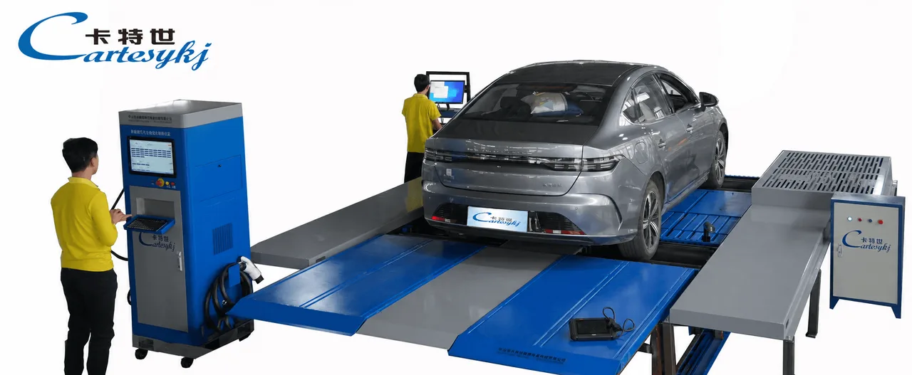
Electric Vehicle Testing Equipment
Electric Vehicle Testing Equipment for Charging and Discharging Safety | CTXNY-3
View ProductRequest a Quote
Request configuration and pricing for your project.
Share your vehicle type, operating requirements, and required configuration for New Energy Vehicle Safety Inspection Equipment for Charging Safety Testing | EVTE-123-S-A-CTEV-3.
Share the project location, vehicle types, inspection scope, applicable standards, target throughput, site conditions and current stage. We will confirm the configuration scope before discussing pricing.