
Brake & Axle (Wheel) Load Testing Equipment
4-in-1 Car Inspection Line | CTGT-3-4
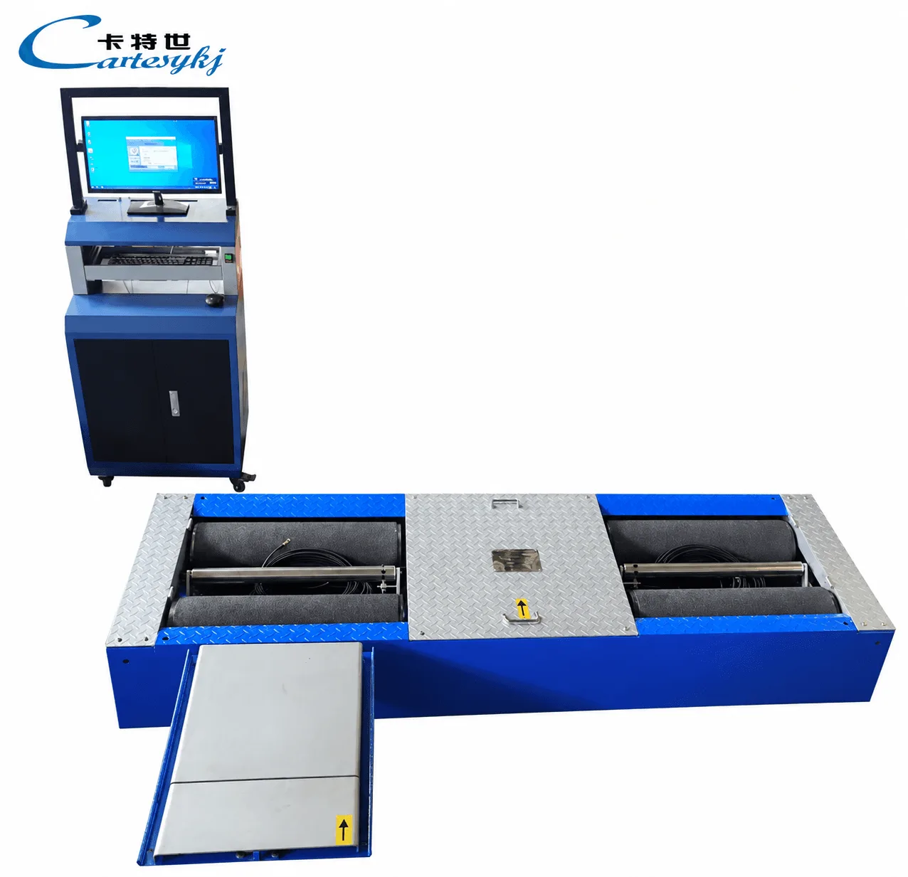
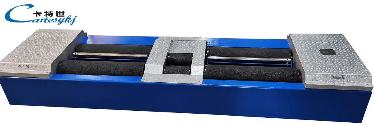
A 4-in-1 Car Inspection Line combines brake testing, suspension testing, wheel or axle-load measurement, and side-slip testing in one inspection system. The CTGT-3-4 and CTGT-3-4C product information lists these four
A 4-in-1 Car Inspection Line combines brake testing, suspension testing, wheel or axle-load measurement, and side-slip testing in one inspection system. The CTGT-3-4 and CTGT-3-4C product information lists these four functions together with computer control, selectable operating modes, and consolidated test reporting.
For workshops and vehicle inspection projects, the configuration brings related measurements into a coordinated testing process. The equipment specification should make clear which measurements each station provides, how the software evaluates results, and which additional functions are included in the selected configuration.
The clearest difference shown between the two models is their side-slip arrangement: the CTGT-3-4 uses a single-plate configuration, while the CTGT-3-4C uses a double-plate configuration.
What the Four Inspection Functions Cover
Brake Tester
The roller brake tester provides the braking measurement function within the line. The product description states a brake-testing speed of up to 2.5 km/h and says that the software can display a brake-force curve during brake application. The technical table lists a brake-force test range of 0–9,000 N for both models.
The curve provides a way to review the recorded brake response during the test. Its interpretation should follow the equipment’s documented measurement method and the evaluation criteria selected for the inspection program.
The stated testing speed describes the brake test condition. It should not be used as a measure of complete-line throughput or the number of vehicles that can be inspected in a working period.
Suspension Tester
Suspension testing is another stated function of the four-in-one system. According to the product description, the software can display a suspension damping or vibration curve while the suspension tester operates.
This provides a view of the test response within the same control system used for the other inspection functions. The final equipment documentation should explain what the curve represents, which measurements are used, and how the result is evaluated.
A curve display should not automatically be described as a universal shock-absorber efficiency measurement or a diagnosis of every suspension component. Those interpretations require support from the selected test method.
Wheel Load Tester Function
Load measurement is the third stated inspection function. The product sheet describes it as axle/load-weight testing. When specifying the Wheel Load Tester function, confirm whether the delivered system reports individual-wheel values, axle totals, or both; the supplied description does not separately define those outputs.
The distinction matters when load data is used in a calculated braking indicator. The measurement source, units, vehicle loading condition, and calculation basis should be identified before interpreting the result.
The final specification should also distinguish the equipment’s measurement range from its permitted structural loading. These describe different aspects of the equipment and should be confirmed independently.
Vehicle Side Slip Tester
Both models include a Vehicle Side Slip Tester function. The technical table identifies a single-plate arrangement for the CTGT-3-4 and a double-plate arrangement for the CTGT-3-4C, with different listed measurement ranges.
The side-slip result should retain the measurement units and interpretation defined by the equipment’s procedure. It should not be relabeled as a complete wheel-alignment assessment or used on its own to identify a specific steering or suspension fault.
Where further alignment work is required, the inspection process should identify the additional measurement or diagnostic procedure.
CTGT-3-4 and CTGT-3-4C Specifications
The following comparison reproduces the clearly identified specifications from the supplied technical table.
| Specification | CTGT-3-4 | CTGT-3-4C |
|---|---|---|
| Side-slip configuration | Single plate | Double plate |
| Listed side-slip test range | ±10 m/km | ±15 m/km |
| Listed side-slip indicating error | ±0.2 m/km | ±0.2 m/km |
| Listed brake-force test range | 0–9,000 N | 0–9,000 N |
| Listed brake-force indicating error | ±3% | ±3% |
| Roller specification | Ø245 × 700 mm | Ø245 × 700 mm |
| Roller center distance | 430 mm | 430 mm |
| Listed wheel-track range | 800–2,200 mm | 800–2,200 mm |
| Listed motor ratings | 3 kW × 2; 2.2 kW × 2 | 3 kW × 2; 2.2 kW × 2 |
| Listed power supply | AC 380 V ±10%, 50 Hz | AC 380 V ±10%, 50 Hz |
Source: supplied CTGT-3-4 / CTGT-3-4C product specification table.
The table shows the same side-slip indicating-error figure for both models. The wider listed measurement range of the CTGT-3-4C should therefore not be presented as evidence of better measurement accuracy.
Some measurement definitions still need clarification. The source does not specify whether the brake-force range applies to an individual channel or an aggregate result, and it does not define the reference basis of the percentage error figure. These details should be confirmed when preparing an acceptance specification.
The listed motor ratings should also remain separate from the facility’s required electrical input specification. The final electrical documentation should establish the actual supply and connection requirements.
Computer Control and Selectable Test Modes
The product description lists industrial-computer control and a choice of manual single-station, semi-automatic, and fully automatic test-operation modes. It also describes configurable evaluation values and software requirements.
These modes should be defined by the activities they cover. The delivered operating procedure should explain which steps involve data acquisition, test sequencing, result evaluation, printing, and operator input.
Vehicle positioning and movement responsibilities should be specified separately. An automatic testing mode should not be interpreted as confirmation that every activity in the inspection process is unattended.
For a workshop evaluating the system, the useful question is how each operating mode fits the intended workflow. The supplier should demonstrate the selected mode using the equipment configuration and vehicle conditions covered by the project.
Consolidated Reports and Searchable Test Records
The supplied description lists automatic result evaluation and printing, consolidated reporting, and searches of test data and records by time, license plate, and vehicle model. It also identifies brake-force and suspension-response curve displays.
These functions should be reviewed together with a sample report. The report should make the measured values, units, evaluated test items, and resulting status understandable to the workshop or inspection operator.
Configurable evaluation values need to match the intended test method and inspection requirements. Software flexibility alone does not establish that a particular configuration is accepted by an inspection program.
If a project requires additional functions—such as a particular data-export format, an external-system interface, or a defined process for retaining repeat tests—those requirements should be included explicitly in the software scope.
Optional Equipment and Testing Upgrades
The four-in-one functions form the core configuration described in the product information. The same material lists additional equipment that can be configured with the line:
Headlight tester.
Gas analyzer.
Opacimeter.
Sound level meter.
Monitoring camera.
Networking interface.
These are described as configurable additions and should be identified separately in the final quotation and equipment list.
The material also mentions an ABS brake-testing upgrade and a 4WD testing upgrade. These should be treated as upgrades whose exact scope requires confirmation. The supplier should identify the supported test functions, vehicle configurations, hardware and software requirements, and operating procedures before either upgrade is specified.
A reference to ABS or 4WD testing should not be expanded into a claim of universal vehicle compatibility or complete diagnostic coverage.
Match the Car Inspection Line to the Facility
When adding this automotive testing equipment to a workshop or inspection facility, review the vehicle requirements, installation arrangement, electrical supply, and reporting needs together.
Vehicle suitability should be checked against the confirmed testing capacity, permitted drive-over loading, wheel-track definition, tire contact requirements, and relevant vehicle geometry. The final specification should identify the conditions under which each rating applies.
The installation package should include a model-specific layout covering the equipment footprint, floor preparation, access, cable routing, and service space. Photographs of an installed line are useful references, but the project still needs the drawings and requirements applicable to the supplied configuration.
Confirm the Electrical Version for the Installation Site
The listed supply is AC 380 V ±10%, 50 Hz. For a U.S. installation, request a factory-confirmed electrical version matched to the facility’s voltage, frequency, phase, and connection requirements. The supplied table does not establish an alternative electrical configuration.
The voltage tolerance should not be interpreted as confirmation of compatibility with a different supply frequency. Any electrical adaptation should be included in the manufacturer’s documented supply scope.
Define Commissioning and Acceptance
Commissioning should demonstrate the agreed inspection functions, selected operating mode, measurement displays, reporting, and any optional interfaces included in the project.
The acceptance plan should distinguish equipment operation from measurement verification. A functioning display or printed report does not, by itself, establish that every measurement meets the required performance criteria.
For regulated inspection work, confirm the requirements of the intended program separately from the base product specification. The equipment configuration, evaluation rules, and reporting arrangement should be reviewed as part of that project.
Define the Final Four-in-One Configuration
The CTGT-3-4 and CTGT-3-4C provide two documented configurations for a four-function inspection system. Their product information supports brake, suspension, axle/load-weight, and side-slip testing, together with computer control and reporting. The specification table distinguishes their single-plate and double-plate side-slip arrangements.
To request a configuration from a vehicle inspection equipment manufacturer, provide the intended vehicle range, expected loading conditions, inspection purpose, available electrical supply, site layout, and reporting requirements.
Ask the manufacturer to identify the selected model, included functions, optional equipment, operating procedures, and measurement definitions in the final technical proposal. This establishes a clear basis for matching the car inspection line to the facility and reviewing the delivered system.
Related Products
Compare related inspection systems
Brake & Axle (Wheel) Load Testing Equipment
Brake Performance Tester for Cars and Motorcycles | CTFZ-10QM
View ProductRequest a Quote
Request configuration and pricing for your project.
Share your vehicle type, operating requirements, and required configuration for 4-in-1 Car Inspection Line | CTGT-3-4.
Share the project location, vehicle types, inspection scope, applicable standards, target throughput, site conditions and current stage. We will confirm the configuration scope before discussing pricing.