Project
Braking Test System for Explosion-proof Trackless Rubber-tired Vehicles
For research and special-purpose military vehicle inspection, a vehicle brake tester should be specified around the required measurements, actual test loading, and vehicle operating conditions. Where roller testing or.
For research and special-purpose military vehicle inspection, a vehicle brake tester should be specified around the required measurements, actual test loading, and vehicle operating conditions. Where roller testing or load simulation is proposed, the solution needs a documented method that connects the recorded brake response to the intended evaluation.
Research teams may need to compare measurements under controlled conditions. Fleet maintenance teams may need to verify a vehicle after service or assess it against an approved inspection procedure. Both applications require identifiable test conditions, appropriate equipment compatibility, and records that explain how each result was obtained.
This discussion covers brake testing of wheeled vehicles for research, maintenance verification, and defined fleet inspection tasks. The supported vehicle configurations and measurement capabilities must be confirmed for the equipment supplied.
Define the Question the Brake Test Must Answer
A useful testing solution begins with a specific measurement objective.
A research program might examine whether brake-force measurements change between defined vehicle configurations or loading conditions. A maintenance inspection might assess whether the required braking measurements satisfy an established acceptance procedure after service.
These applications can require different data. A maintenance record may need the measured values, evaluation criteria, and outcome. A research study may additionally require individual measurement channels, time-based traces, or the relationship between brake input and recorded response.
Before selecting equipment, define the required outputs and how they will be used. If the project requires brake-force distribution, left-to-right comparison, or a load-normalized indicator, identify the measurements and calculations needed to produce that result.
The test objective should also establish the boundary of the conclusion. Results from a specified brake test support conclusions about that test under its recorded conditions. Additional claims about vehicle performance require their own applicable methods and evidence.
Understand What a Roller Brake Tester Measures
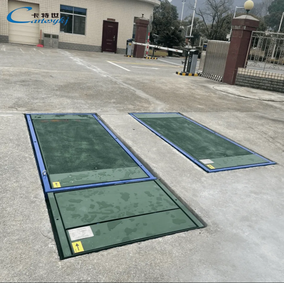
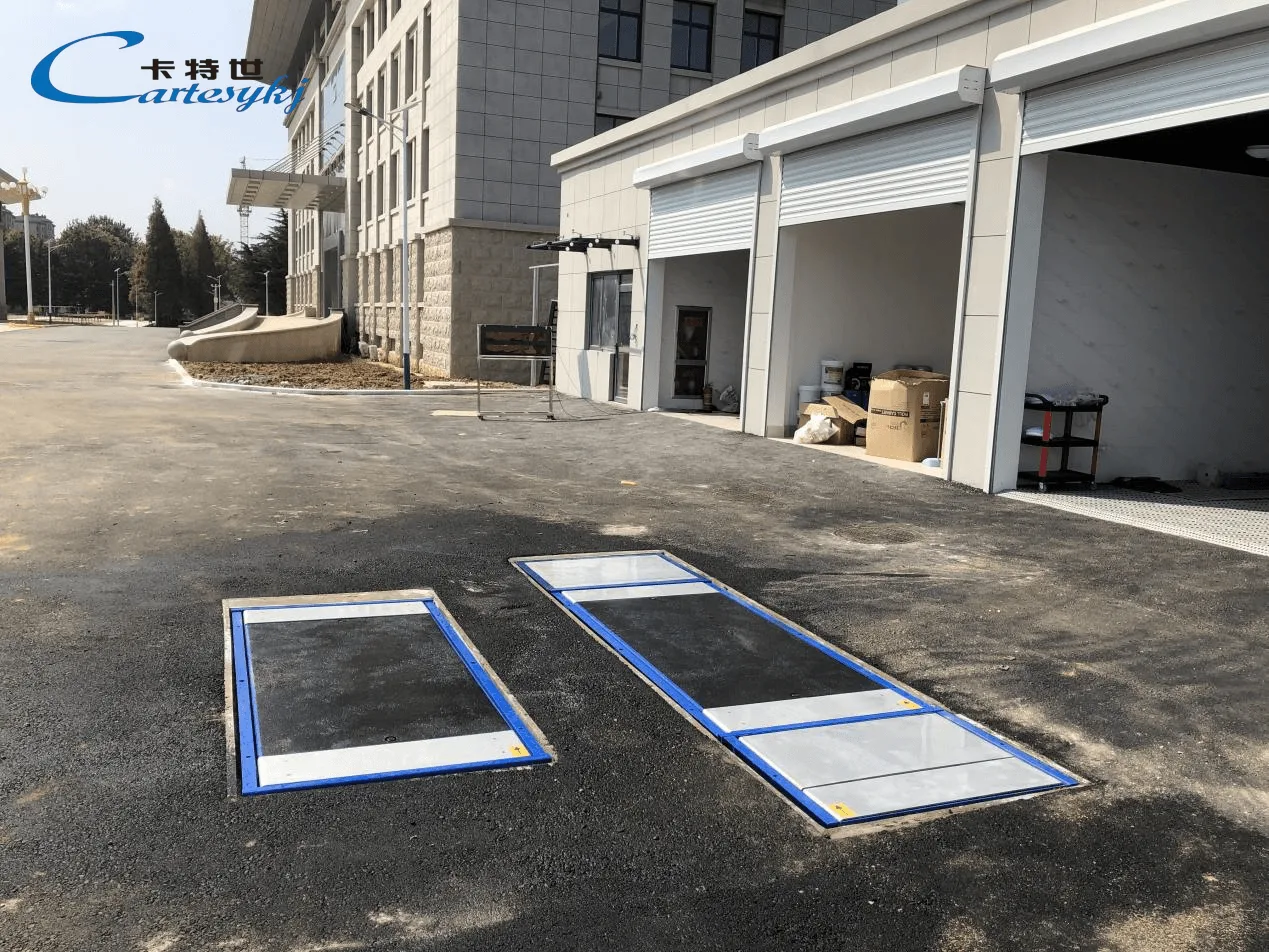
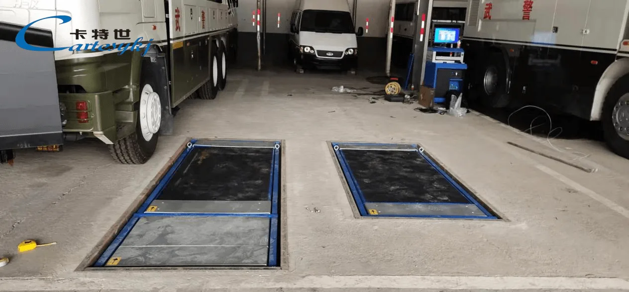
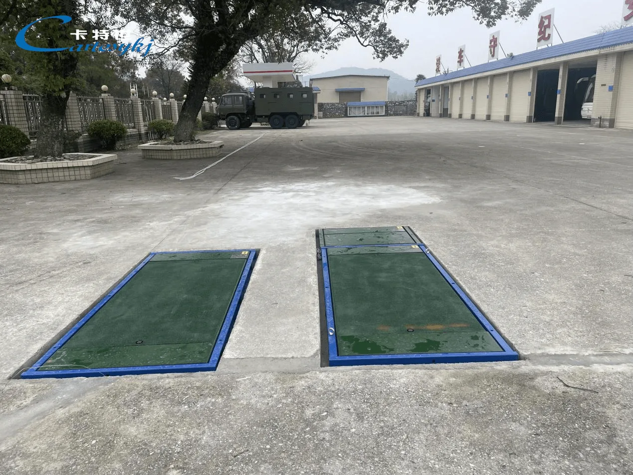
In a roller-based brake test, the supported wheels rotate on roller sets while braking response is measured under the specified procedure. The equipment’s design determines the available measurement channels, processing methods, and reported outputs.
For a proposed roller brake tester, the technical documentation should identify how braking force is determined and which wheel or axle results are available. It should also explain the conditions under which a measurement is considered valid.
This information matters when comparing results. Values obtained using different processing methods, test conditions, or measurement channels should not be treated as directly interchangeable without a documented basis.
The report should describe the measured quantity accurately. A roller brake-force result should not be presented as a direct measurement of road stopping distance, high-speed braking capability, or sustained thermal performance. Those properties require separately defined test methods.
Keep Measurement and Calculation Separate
A brake performance tester may provide measured values and calculated indicators, depending on its configuration. The specification should distinguish between them.
Where an evaluation uses braking efficiency or another load-normalized result, define
The brake-force values included in the calculation.
The required load reference and its source.
The units and calculation convention.
Any filtering, peak selection, or channel-combination rules.
The conditions under which the result may be evaluated.
The load reference might be measured during the test setup or obtained from another source permitted by the procedure. Its origin should remain visible in the record.
Measured test loading, entered vehicle data, and rated vehicle mass should not be substituted for one another without justification from the selected method. An apparently complete percentage result can still be unsuitable for evaluation if its load basis is unclear.
Assess a Load Simulation Brake Tester with Lifting System
A proposal described as a Load Simulation Brake Tester with Lifting System needs a clear explanation of both functions. The product name alone does not establish how loading is simulated, what the lifting mechanism moves, or which vehicle configurations the arrangement supports.
The technical proposal should explain what changes during lifting and how that change relates to the test condition. It should identify whether the lifting function positions equipment, changes a vehicle support condition, contributes to a defined loading method, or performs another documented task.
Lifting movement and applied load need separate specifications. A lifting position or height does not, by itself, establish the load acting at the tested wheels.
Confirm How the Test Load Is Established
Where the system changes the loading condition at a tested axle, the documentation should explain how that condition is produced, determined, and recorded.
The following items provide a practical basis for reviewing the proposed arrangement
| Function or condition | Technical information to request |
|---|---|
| Lifting function | Drawings and an operating description identifying the moving assembly, supported components, and permitted positions. |
| Load-simulation method | An explanation of how the relevant loading condition is created or changed and which quantity is controlled. |
| Test-load measurement | The source of the load value, measurement channels, units, applicable range, and verification method. |
| Vehicle compatibility | Supported wheel arrangements, axle geometry, loading conditions, and vehicle positioning requirements. |
| Equipment limits | Applicable wheel, axle, lifting-assembly, and test-system limits under the proposed procedure. |
| Invalid conditions | The defined response when the required loading or measurement conditions cannot be established. |
The proposal should make the relationship between the loading mechanism and measured brake response understandable. If a study compares results at different simulated conditions, each result needs an identifiable loading condition and a consistent evaluation method.
Define the Limits of the Simulation
A simulated axle-loading condition should be reported as the specific condition established by the equipment.
A change in load at a tested axle does not, by itself, reproduce the complete effect of carrying a payload. Whole-vehicle mass distribution, center of gravity, dynamic load transfer, road contact, and braking-energy demand remain separate considerations.
For that reason, any claim that the simulated condition represents a particular loaded-vehicle condition needs justification for the property being evaluated. The scope of that relationship should be stated in the test procedure and retained with the results.
This distinction allows load simulation to serve a defined research or inspection purpose without extending the conclusion beyond the evidence.
Verify Compatibility With the Actual Vehicle Configuration
Special-purpose military vehicles should be assessed at the configuration level. A general equipment category or capacity label is insufficient to establish compatibility with every vehicle in a fleet.
The review should cover individual wheel loads, axle loads, tire dimensions, single or dual wheel arrangements, relevant track widths, and the geometry needed to position the vehicle on the tester. Equipment access and exit requirements should also be checked against the facility layout.
Structural capacity and measurement capability require separate attention. The equipment must be suitable for the loading involved, while its measurement system must also support the range and performance required by the test program.
Drivetrain and control-system compatibility need their own confirmation. Multi-axle layouts, connected drive axles, electronically controlled braking functions, and other vehicle features may affect the permitted test procedure. The vehicle and equipment documentation should establish the appropriate test conditions.
Generic instructions to disable vehicle functions should not replace an approved procedure. Where a particular test mode is required, its applicability and use need confirmation for the vehicle concerned.
The same boundary applies to tracked vehicles. Compatibility established for wheeled vehicles should not be extended to tracked configurations without separate technical evidence.
Design Research Comparisons Around Controlled Conditions
Research results become more useful when the record explains both the measurement and the conditions that produced it.
The test plan should identify which variables must be controlled and which must be recorded. Depending on the investigation, these may include vehicle configuration, loading, tire setup, initial brake condition, tester settings, and the brake input used during the measurement.
If the study compares results at a specified brake input, define how that input is determined. If the analysis requires time-based behavior, confirm that the necessary measurement channels and timing information are available.
The data requirements should be settled before equipment selection. A summary result and a time-based measurement record support different types of analysis.
Preserve Original Values and Processing Information
Where data export is required, confirm which values are available and how they are represented. Original instrument outputs should remain distinguishable from unit conversions, calculated indicators, and subsequent analysis.
The records should identify relevant software or calculation versions. If processing changes during a research program, the change needs to be visible so reviewers can determine whether earlier and later results remain comparable.
For load-simulation studies, preserve the loading condition associated with each brake measurement. The comparison should use a consistent method or explain how differences between methods were addressed.
Evaluate Repeatability and Accuracy Separately
Repeated readings provide information about consistency under the stated conditions. They do not independently establish measurement accuracy.
Request the calibration information and measurement-performance evidence applicable to the supplied configuration. Where the research program requires measurement uncertainty information, define that requirement as part of the technical scope.
The test plan should also explain how repeated runs, interrupted tests, and excluded observations will be handled. Keeping these decisions documented allows the final analysis to be reviewed without relying on an unexplained selection of results.
Integrate Brake Testing Into the Inspection Line
When the brake tester forms part of an Inspection Line, the workflow should connect each test attempt to the correct vehicle, procedure, loading information, and result.
A practical record should identify the vehicle configuration, equipment used, test conditions, measured values, calculation rules, and outcome. If loading information comes from another device or system, the interface should preserve its source and association with the brake test.
The workflow should distinguish between a valid result outside an acceptance limit, an invalid measurement, and an incomplete test. These conditions require different handling.
For example, an unavailable load value may prevent a particular calculation from being completed even when brake-force data has been recorded. The report should preserve the available measurement and explain which evaluation remains unresolved.
Retesting should create a linked record with its own conditions and outcome. Earlier attempts, reasons for repetition, and relevant maintenance actions should remain identifiable.
Data reporting and equipment control should also have separate scopes. Transferring a completed report does not establish that the receiving system can operate the tester or authorize the vehicle’s release. Any required control, reporting, or approval interfaces need explicit confirmation.
Verify the Delivered System Against the Agreed Scope
Project acceptance should demonstrate the functions included in the supplied configuration under the vehicle and test conditions covered by the agreement.
For a roller system, this includes the measurement process, data interpretation, required calculations, and reporting. For a load-simulation arrangement, acceptance should also address how the loading condition is established, measured, associated with the brake result, and kept within the documented operating scope.
The acceptance procedure should include the exception paths relevant to the facility. These may involve an interrupted test, missing input data, an unresolved loading condition, or a repeated inspection after maintenance.
Software demonstrations and measurement verification should remain distinguishable. Showing that a report or calculation works as specified does not establish the measurement performance of the connected equipment.
For research applications, confirm that the delivered data supports the intended analysis. For fleet inspection, confirm that the records support the approved evaluation and review process.
Claims about specialized vehicle compatibility or military qualification require evidence applicable to the supplied system. The intended customer or application does not establish those capabilities.
Specify the Solution Around a Documented Test Method
A vehicle brake tester solution for research and special-purpose military vehicles should connect a defined measurement task with suitable equipment, confirmed vehicle compatibility, and traceable test records.
Roller testing requires a clear description of the measured brake response and its evaluation limits. Load simulation requires a documented loading method and an identifiable test condition. A lifting system requires its own functional explanation and operating limits.
To develop a project-specific proposal, provide the vehicle configurations, expected test loading, required measurements, evaluation procedures, and data needs. Request a corresponding equipment scope, compatibility statement, loading and lifting documentation, sample records, and acceptance plan. These materials provide a concrete basis for assessing whether the proposed system supports the research or inspection task.
Project imagery