Project
New Energy Vehicle Testing Solutions with a 4WD Chassis Dynamometer
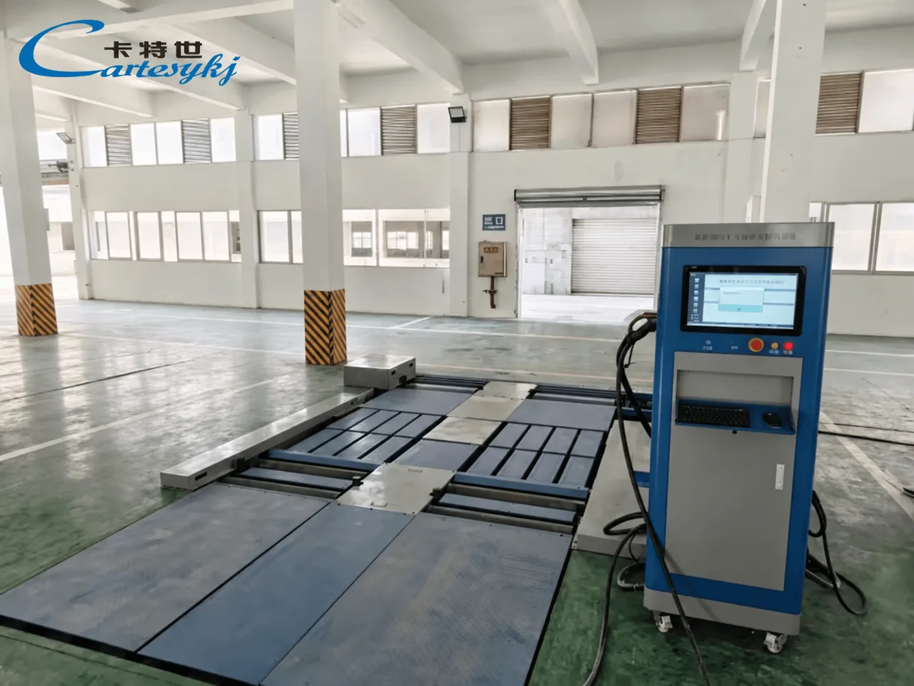
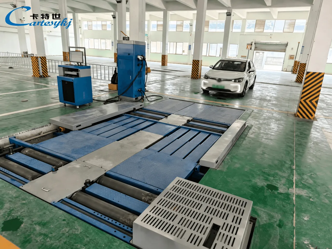
A 4WD chassis dynamometer can provide the performance-testing function within a new energy vehicle testing solution. For an electric vehicle with driven wheels on both axles, the equipment must support the intended.
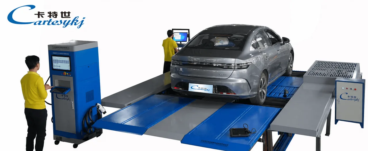
A 4WD chassis dynamometer can provide the performance-testing function within a new energy vehicle testing solution. For an electric vehicle with driven wheels on both axles, the equipment must support the intended drive arrangement, manage the required relationship between the axle stations, and produce clearly defined measurements.
The “4WD” designation alone does not establish compatibility with every electric all-wheel-drive system. Vehicle dimensions, loads, drivetrain controls, and the selected test procedure all need to match the proposed configuration.
The focus here is performance assessment of battery-electric road vehicles within a broader inspection or evaluation program. Other powertrain types require their own documented test scope.
Define the Role of the Dynamometer in the Testing Solution
A chassis dynamometer evaluates specified vehicle performance through the interaction between the driven wheels and the test system.
In a roller chassis dynamometer, the tires act on rollers. Depending on the equipment’s design, the system measures or calculates performance quantities under the selected operating conditions.
The proposal should identify exactly what the system measures, how calculated outputs are obtained, and which operating modes are supported. These details determine whether the equipment can answer the facility’s intended testing questions.
| Testing Objective | Capability to Confirm | Information Needed to Interpret the Result |
|---|---|---|
| Evaluate wheel-output performance | Suitable measurement functions and supported operating range. | Measurement reference point, calculation method, vehicle conditions, and units. |
| Assess performance at defined operating points | The required load-control functions. | Control method, supported conditions, and test procedure. |
| Examine front- and rear-axle behavior | Appropriate measurement channels and coordinated data acquisition. | Axle identification, timing, and the method used to combine results. |
| Assess a specified deceleration or regenerative function | Operating modes suitable for that particular procedure. | Torque and power directions, vehicle state, and measurement scope. |
These are capabilities to establish for the proposed configuration. They should not be assumed from the equipment category or product name.
Match the Equipment to the Vehicle’s Driven-Axle Arrangement
Electric vehicles can have different drive configurations. The project specification should identify which wheels are driven and how the intended test operates them.
Where the front and rear drives are controlled separately, the proposal should explain how the dynamometer supports that arrangement. Compatibility with one all-wheel-drive vehicle does not establish compatibility with every vehicle using a similar marketing description.
The equipment documentation should address relevant wheelbase, track width, tire contact, wheel loads, and positioning requirements. Support and restraint arrangements should follow the documented application for the selected vehicle and test system.
Define Front- and Rear-Roller Coordination
The system should document how it establishes the required relationship between front- and rear-roller speeds and loads.
The design may use a particular mechanical connection, electronic control arrangement, or another documented approach. The proposal should identify the actual design and explain its suitability for the intended procedure.
The required relationship should not be reduced to a universal instruction that all rollers must have identical rotational speed. Roller rotational speed and the vehicle-speed value derived by the system are distinct quantities that should be clearly identified.
The vehicle and equipment documentation should also establish any required test mode. Compatibility should be demonstrated through a supported procedure rather than an improvised change to vehicle controls.
Distinguish Per-Axle and Combined Ratings
Where the manufacturer provides both axle-specific and combined ratings, the proposal should preserve that distinction.
A combined rating should not be used as a substitute for checking the capability of each axle station under the intended test conditions. The documentation should also distinguish continuous and time-limited capabilities where those ratings are defined.
This allows the facility to evaluate the proposed equipment against the actual test requirement without assuming that load or power is always distributed equally between the axles.
Interpret Power and Torque Results at the Correct Measurement Point
An automotive dyno report should explain where each power or torque result is assessed and how it is obtained.
The report may contain directly measured quantities, calculated outputs, or estimates based on a documented model. Those categories should remain identifiable.
A roller-derived wheel-output result should not automatically be labeled as motor-shaft output. Any estimate of motor output requires a defined method and supporting assumptions. An arbitrary drivetrain-loss percentage should not be applied to create a more favorable result.
Comparisons with vehicle or motor specifications also need matching measurement definitions and operating conditions.
Combine Axle Results Using a Defined Method
If the system reports total vehicle output, the documentation should explain how the axle results are combined.
The relevant data must be associated with the same test and interpreted according to the system’s method. Separate front- and rear-axle peaks should not simply be added unless the data and calculation justify that combined value.
A useful report should show whether the displayed result represents an individual axle, a synchronized combined output, or another defined quantity.
Keep Mechanical Output Separate From Electrical Input
Mechanical performance at the wheels does not directly establish battery electrical input.
An efficiency assessment requires defined input and output measurements, compatible units, and a clear system boundary. A wheel-power result alone cannot establish how efficiently the complete vehicle converts battery energy into motion.
Similarly, dynamometer performance does not independently establish battery capacity, remaining battery life, or electrical insulation condition. Those questions require separate evidence where they are included in the project.
Confirm Load-Control and Regenerative-Testing Functions
The intended test determines which operating functions the dynamometer needs.
A procedure requiring a maintained operating point or controlled resistance needs equipment that supports those conditions. Road-load reproduction, automated drive sequences, and other simulation functions should be confirmed individually for the proposed configuration.
A roller-based design does not automatically provide every form of load control or reproduce every road condition.
Specify the Required Operating Modes
The technical proposal should connect each planned procedure to the relevant control and measurement functions.
For a defined load test, it should identify how the required condition is established and maintained. For a changing test sequence, it should explain the supported control method and how the resulting measurements are recorded.
The test specification should remain within the equipment’s documented operating range and the vehicle’s supported procedure.
Define Regenerative Assessment Separately
If the project includes regenerative-deceleration testing, the proposed system must support the particular procedure.
The ability to absorb propulsion power does not, by itself, establish active motoring capability or suitability for every regenerative test. The proposal should identify the required torque and power directions and show how the selected configuration supports them.
The measurement scope must also remain clear. Mechanical deceleration data does not independently measure the electrical energy recovered by the battery.
Where recovered electrical energy is part of the assessment, the additional measurement method should be specified and associated with the same test conditions.
Document the Electric Vehicle’s Test Conditions
Electric vehicle performance results need a defined vehicle state.
Depending on the selected procedure, relevant information may include battery state of charge, available battery or drive-system temperature information, selected operating mode, and vehicle settings that affect the assessment.
The procedure should identify which conditions must be controlled and which need to be recorded. A universal charge level, preparation time, or temperature range should not be assigned across different models without supporting documentation.
Tire and vehicle setup requirements should also follow the applicable equipment and vehicle instructions.
For repeated tests, the report should make it possible to determine whether the relevant conditions were comparable. A difference between two curves should be interpreted with that context rather than attributed automatically to a change in vehicle performance.
Any required test mode should remain within the documented procedure. The equipment proposal should not depend on a generic instruction to disable traction, stability, or other vehicle controls.
Integrate the Dynamometer With the Wider Inspection System
When a dynamometer forms part of a broader new energy vehicle inspection equipment package, its role should remain explicit.
Performance assessment is one function within the solution. Brake testing, speedometer verification, electrical assessment, and battery diagnostics each need their own supported methods where they are included.
A shared display or reporting system should not imply that the dynamometer performs every inspection function. Additional capabilities must be documented for the specific configuration.
Preserve the Source of Each Result
The reporting system should associate each measurement with the vehicle, equipment, and procedure that produced it.
Where several instruments contribute to one report, specify how their records will be transferred and combined. Automatic identification, direct communication, and common report generation are functions to verify rather than assume.
The report should distinguish
Direct measurements and their units.
Calculated or corrected outputs.
Individual-axle and combined results.
Relevant vehicle conditions.
Applied acceptance criteria.
Tests that were omitted, incomplete, or outside the selected scope.
A sample report can help the facility evaluate whether the proposed integration preserves enough information to interpret the results.
Establish Requirements for the U.S. Application
For a U.S. facility, identify the intended purpose before defining acceptance limits.
The equipment may support performance evaluation, service diagnosis, a customer’s test specification, or another documented program. The applicable vehicle category, procedure, and reporting requirements should be established for that use.
A successful dynamometer test does not, by itself, establish complete vehicle safety or acceptance for every inspection purpose.
Where the project requires acceptance by a program administrator or another responsible body, identify the necessary evidence and process before relying on the installation for that application.
The equipment’s supported functions and the project’s acceptance requirements should be evaluated separately, then connected through the documented test method.
Request a Configuration Proposal Based on the Actual Test Program
Provide the vehicle inspection equipment supplier with the intended vehicle range, driven-axle arrangements, testing objectives, and reporting requirements.
Request a proposal that identifies the supported vehicle configurations, front- and rear-roller control arrangement, measurement methods, load-control functions, and any regenerative-testing capability.
The proposal should also include installation requirements, operating limitations, calibration documentation, vehicle setup procedures, and sample reports. Any optional electrical measurement or inspection functions should be listed separately.
Where a demonstration or acceptance test is arranged, use agreed vehicles and procedures representative of the intended application. Review the complete process, including axle coordination, data interpretation, and the final report.
A suitable 4WD chassis dynamometer connects the vehicle’s drive arrangement to a supported operating method and clearly defined performance results. Establishing those connections provides a practical basis for evaluating its role within a new energy vehicle testing solution.
Project imagery