Project
Design Proposal for a Mobile Vehicle Safety Performance Inspection Line
A mobile vehicle inspection line brings a defined set of vehicle tests to different locations. A complete solution needs more than transportable instruments: it requires compatible test modules, a documented deployment.
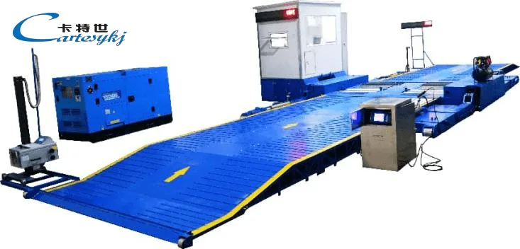
A mobile vehicle inspection line brings a defined set of vehicle tests to different locations. A complete solution needs more than transportable instruments: it requires compatible test modules, a documented deployment method, suitable site conditions, and a consistent process for recording and evaluating results.
For inspection operators and fleet service managers, the first task is to define which vehicles will be tested, which measurements are required, and where inspections will take place. A brake tester and a Vehicle Side Slip Tester may form part of the configuration, but their inclusion and capabilities must be confirmed for the proposed system.
The equipment’s transport arrangement, working installation, and inspection functions should be specified separately. This makes it possible to assess whether the line can support the intended service at each location.
Define How the Mobile Inspection Line Will Be Deployed
“Mobile” should describe a documented deployment arrangement.
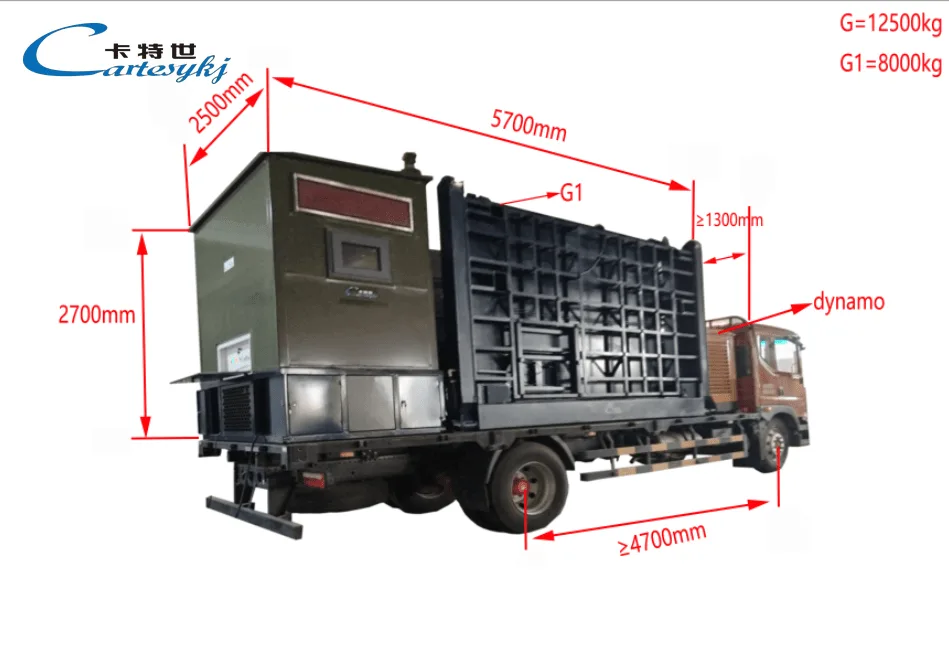
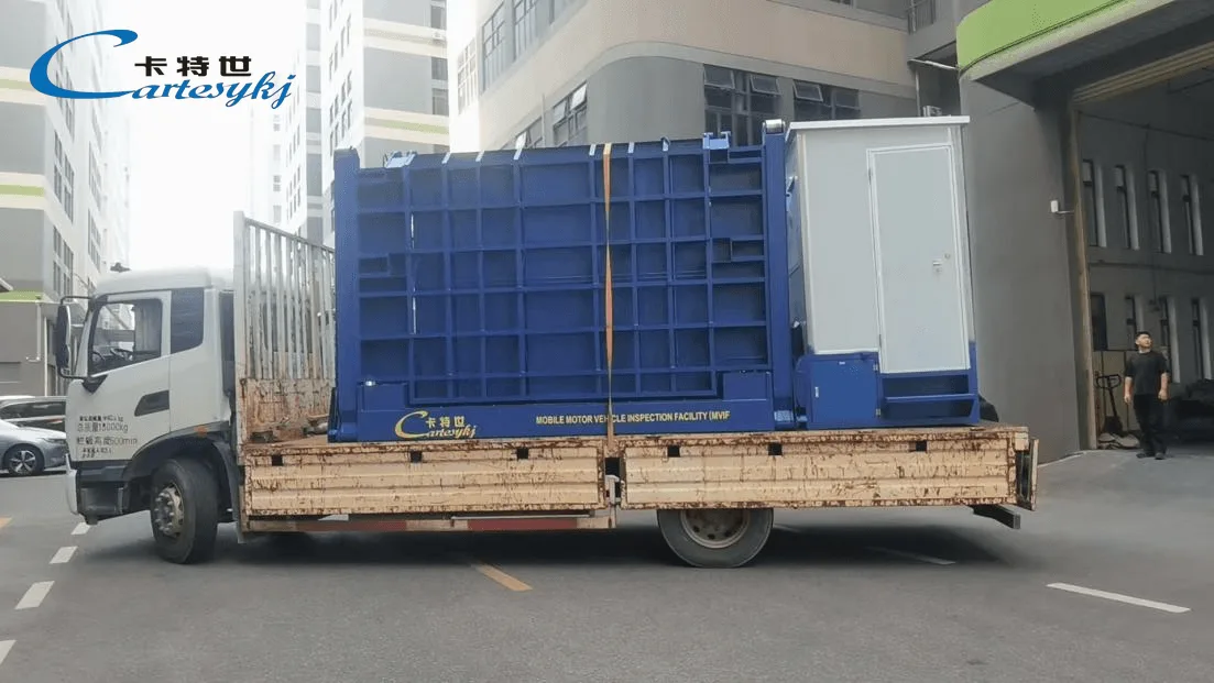
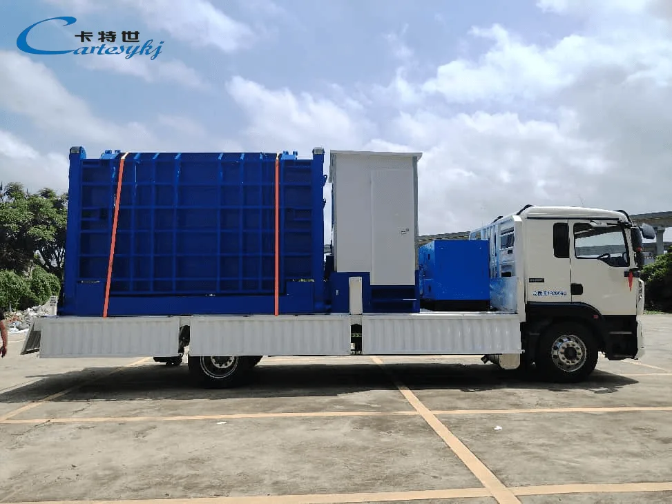
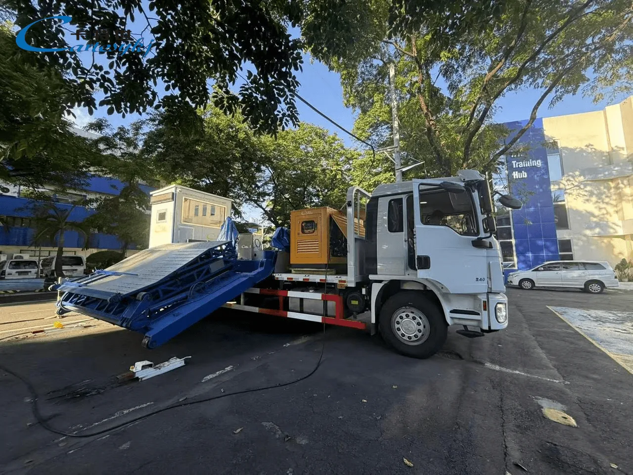
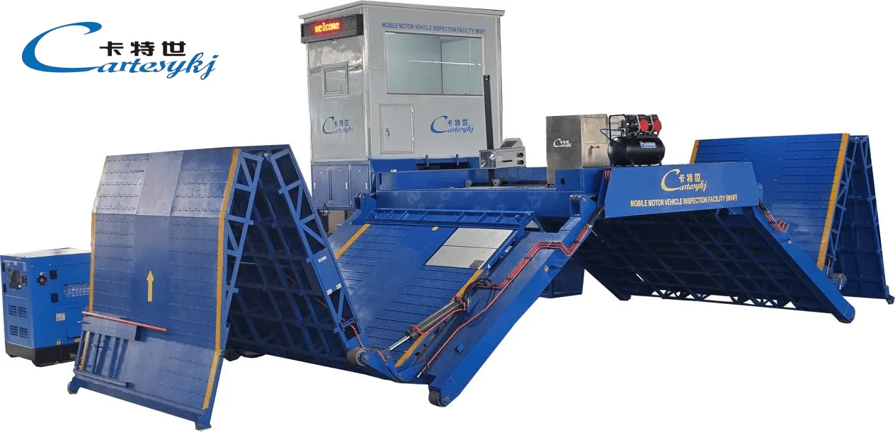
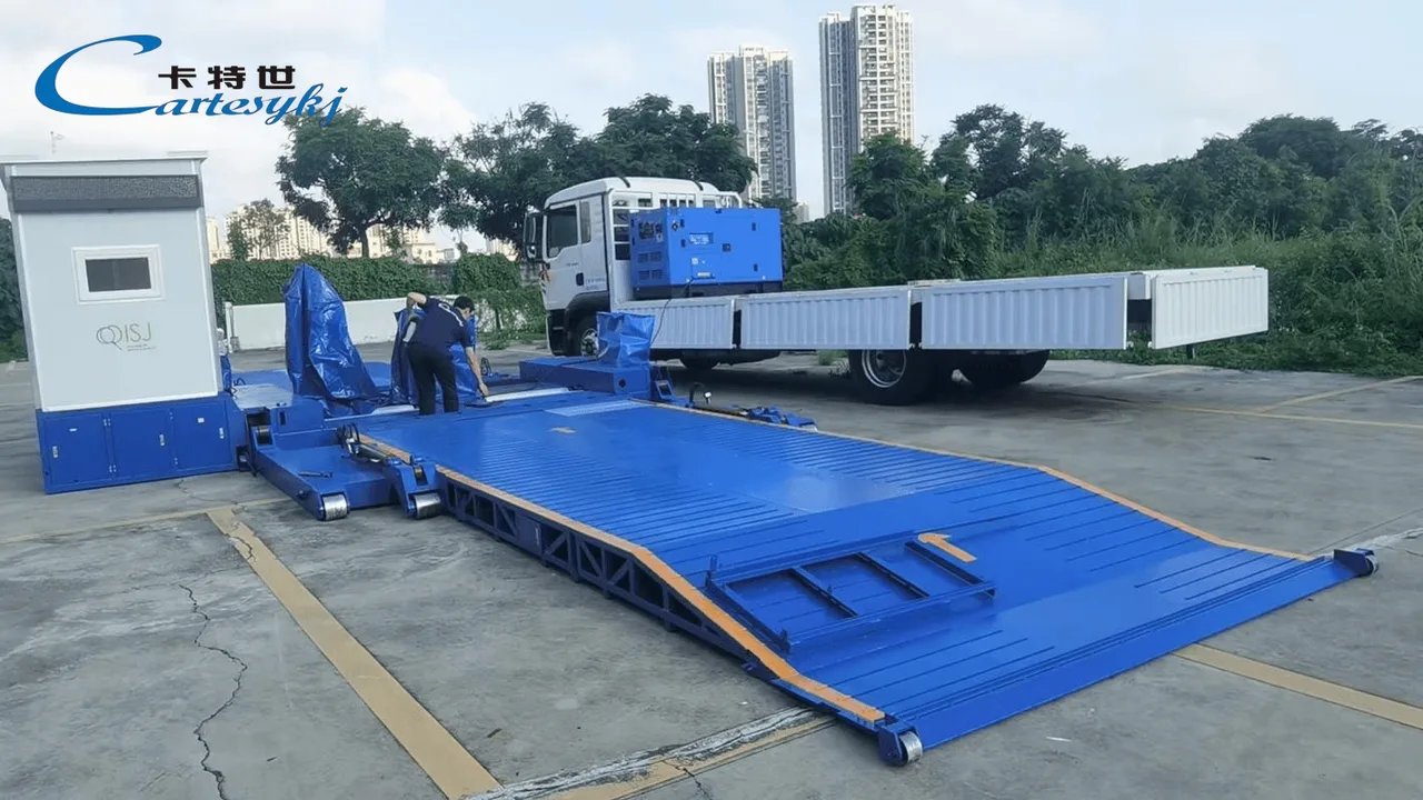
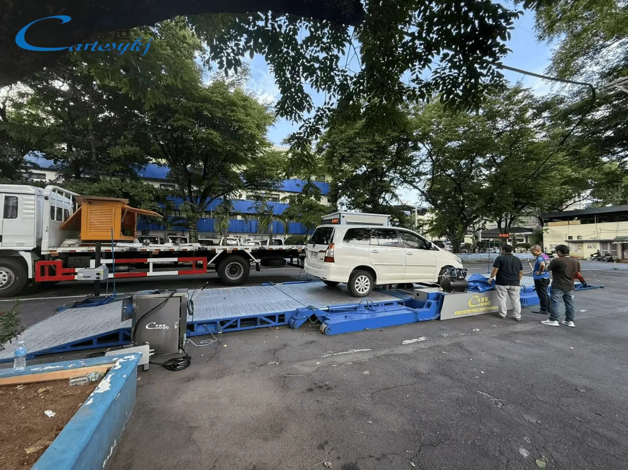
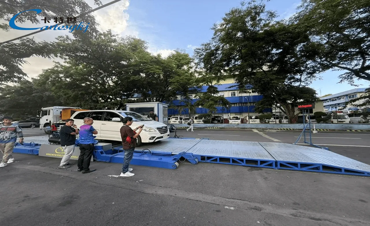
A proposal may involve separately transported test modules, equipment installed on a trailer, or a vehicle-mounted configuration. These arrangements create different requirements for transport, positioning, vehicle access, and site support. The supplier’s drawings and operating documentation should establish which arrangement is actually offered.
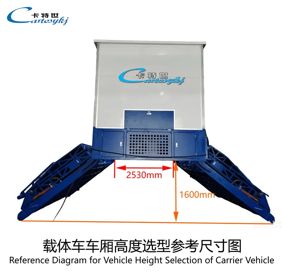
For separately transported modules, the deployment plan needs to cover unloading, positioning, connection, verification, and removal. If equipment remains installed on a carrier during testing, the proposal should explain the working configuration, support requirements, and how the vehicle under inspection enters and leaves the test area.
The specification should identify which items travel with the line and which must be available at the destination. External lifting equipment, transport vehicles, power supplies, and other services should be included in that review where required.
Transportability does not establish self-propelled movement or readiness to test immediately after arrival. Each proposed configuration needs a clear transition from its transport condition to its approved working condition.
Build the Line Around the Required Inspection Items
The inspection program should determine the equipment list.
For every required test, identify the measurement method, supported vehicle configurations, reported quantities, and evaluation criteria. This creates a defined scope for the mobile line and prevents an equipment package from being treated as a complete inspection program without checking its contents.
Additional vehicle testing equipment should be included where it serves an identified inspection requirement and can operate within the proposed deployment arrangement.
Brake Tester
The brake tester specification should identify the test method before addressing its mobile installation. Different methods have different working arrangements, measurement outputs, and installation requirements.
Confirm the supported individual-wheel and axle loads, tire arrangements, relevant vehicle dimensions, and drivetrain compatibility. These requirements should be assessed against the actual vehicles expected at the inspection sites.
The documentation should also distinguish measured values from calculated indicators. If the report includes braking efficiency or another load-normalized result, identify the load reference, its source, and the calculation used.
A brake-force measurement should remain traceable to its test conditions and evaluation method. The mobile format should not change the meaning of the reported result or introduce unsupported assumptions about vehicle compatibility.
Where load information comes from another instrument or an authorized data source, the inspection workflow should preserve that source and associate it with the correct test attempt.
Vehicle Side Slip Tester
A Vehicle Side Slip Tester should be treated as a distinct function within the proposed line. Its presence is not established by the inclusion of a brake station, even where the equipment is presented as an integrated package.
The technical scope should identify the side-slip measurement method, reported quantity, units, direction or sign convention, and conditions required for a valid result. Installation and vehicle-approach requirements should follow the documentation for the supplied model.
The report should retain the original meaning of the measurement. Side-slip data should not be relabeled as toe, camber, or a complete wheel-alignment assessment without supporting technical evidence. A specific steering or suspension diagnosis also requires an appropriate diagnostic basis.
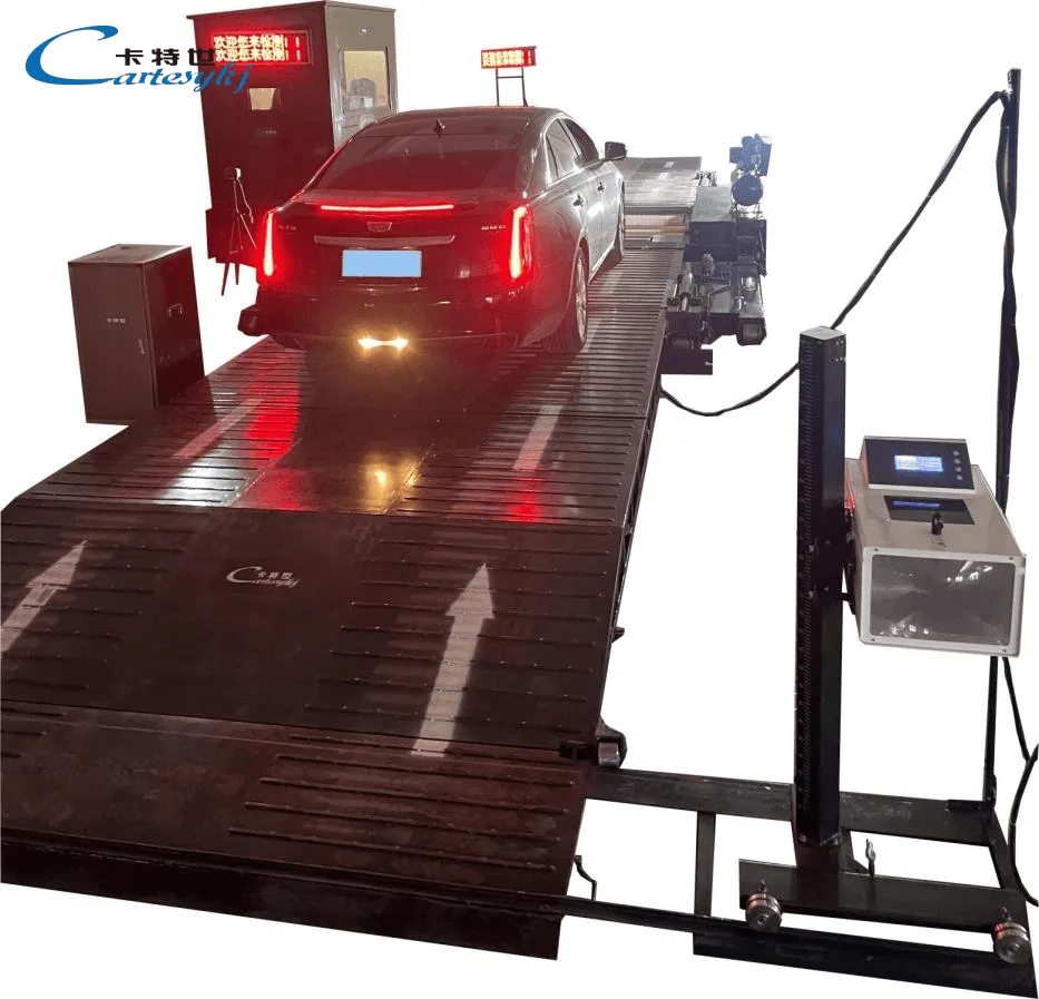
For a mobile installation, the setup procedure should explain how the required measuring arrangement and vehicle path are established at each site.
Match Each Site to the Equipment and Vehicle Requirements
A mobile inspection line still needs a suitable working location. The site review should cover the installed equipment, the vehicles under test, and the space needed to operate the inspection process.
Equipment transport weight and vehicle test loading are different planning inputs. The site assessment should use the relevant installation and loading information supplied for the system.
The following areas should be resolved before deployment
| Site consideration | Information to confirm |
|---|---|
| Ground and support | Required bearing capacity, support arrangement, surface condition, and levelness under the equipment’s installation instructions. |
| Vehicle access | Entry and exit geometry, any required ramps, ground clearance, turning space, and the supported vehicle dimensions. |
| Working area | Space for the test modules, operator positions, vehicle movement, and any required separation between activities. |
| Utilities | Electrical supply requirements, connection arrangements, and any other services required by the supplied configuration. |
| Environmental conditions | Permitted operating conditions and the suitability of the complete installation for the proposed indoor or outdoor location. |
| Communications | Connectivity required for the agreed reporting and data-transfer functions. |
A location described as paved or flat still needs to be assessed against the equipment’s documented requirements. Likewise, a transportable configuration should not be assumed to require no anchoring, support work, or other site preparation.
Outdoor deployment requires confirmation of the applicable operating conditions for the measuring equipment, electrical connections, controls, and associated components. Transport, storage, and operating limits should remain distinguishable.
If generator operation is required, confirm that the proposed supply meets the system’s documented electrical requirements. The need for generator compatibility should be part of the project specification rather than an assumption made after delivery.
Use a Consistent Setup and Verification Process
The deployment procedure should explain how the system is prepared for testing at a new location.
This includes the required installation checks, equipment connections, configuration settings, and measurement checks. The procedure should identify who completes each activity and what evidence confirms that the line is ready for use.
Follow the documented checks required after transport and setup, including any specified measurement verification or recalibration. A universal rule that every move requires full recalibration—or that relocation never affects measurement validity—should not replace the instructions applicable to the equipment.
The readiness decision should address both the site and the instruments. Completing the physical installation is only one part of establishing a valid test arrangement.
Useful deployment records may include the location, equipment identities, installed configuration, completed checks, and relevant calibration references. These records provide context when measurements from different sites are reviewed later.
The removal and transport procedure should also be defined. Packing, securing, handling, and storage requirements need to follow the equipment documentation so that the next deployment begins from a known condition.
Keep Results Connected to the Vehicle, Site, and Equipment
A mobile inspection record should make it possible to identify where and how the test was performed.
For each test attempt, the proposed record should include the vehicle identity, relevant configuration, site, date, equipment used, measured values, units, and applicable evaluation rules. Where test conditions affect interpretation, those conditions should be retained as well.
The workflow should distinguish between
A valid result that satisfies the applicable criteria.
A valid result outside the acceptance limits.
An invalid measurement that cannot support an evaluation.
An incomplete inspection with outstanding test items.
Missing data should remain visible. For example, if a required load value is unavailable, the system should explain which calculation or decision cannot be completed rather than silently treating the missing value as zero.
Repeat tests should create linked records that preserve the earlier attempt. This allows reviewers to follow the inspection history and understand the reason for a later result.
Confirm Connectivity and Reporting Functions
The reporting arrangement should match the conditions expected at the inspection sites.
If the service needs to continue without a reliable internet connection, offline operation must be an explicitly confirmed function. The specification should address local record storage, identification of pending transfers, recovery after an interruption, and handling of repeated submissions where those functions are required.
Automatic vehicle identification, centralized reporting, and interfaces to external systems also need their own documented scope. They should not be inferred from the presence of inspection software.
For reports intended for an official inspection program, confirm the required equipment, methods, deployment arrangements, and reporting format with the responsible program. A generated report alone does not establish acceptance of the complete mobile service.
Plan Capacity Around the Whole Deployment Cycle
The useful capacity of a mobile service depends on more than the duration of an individual measurement.
Planning should account for travel, site access, installation, required verification, vehicle identification, testing, exception handling, and removal. The intended vehicle mix and the conditions at each destination also need to be included.
A quoted test duration should therefore be accompanied by a clear explanation of what it covers. It may refer to one measurement, a complete inspection sequence, or a broader operating cycle. These are different planning measures.
Ask for capacity estimates based on the proposed configuration and documented assumptions. The estimate should identify which activities occur before the first inspection, which repeat for every vehicle, and which are required before departure.
Where sites differ, use a deployment plan for each location. Shared equipment can support a common inspection method, but each site still needs its own access, utility, and setup arrangements.
This gives operators a more useful basis for scheduling than an unsupported claim about inspections per hour or immediate setup.
Turn Deployment Requirements Into a Defined Solution
A mobile vehicle inspection line should connect the required tests with suitable equipment, a workable transport arrangement, verified site conditions, and traceable records.
The brake tester needs a defined measurement method and confirmed vehicle compatibility. The side-slip module needs its own installation requirements and interpretation. The complete line needs a documented process for transport, setup, verification, inspection, and relocation.
To develop a project-specific proposal, provide the intended vehicle configurations, required inspection items, destination-site information, available utilities, and reporting needs. Ask the vehicle inspection equipment supplier to return a proposed layout, equipment scope, transport and installation requirements, setup responsibilities, sample records, and an acceptance procedure.
These documents make it possible to assess the mobile solution as a complete operating arrangement and establish what must be ready at each inspection location.
Project imagery