Project
Electric Motorcycle Testing Solutions with a Motorcycle Chassis Dynamometer
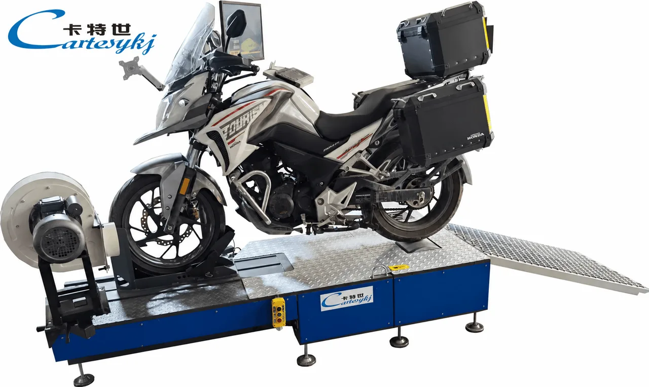
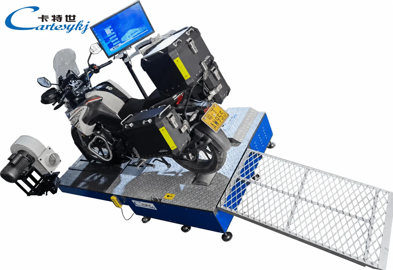
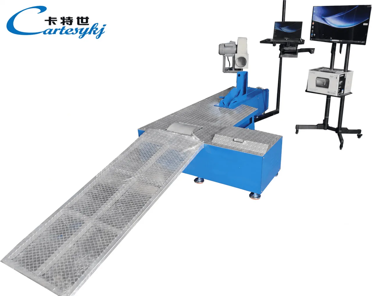
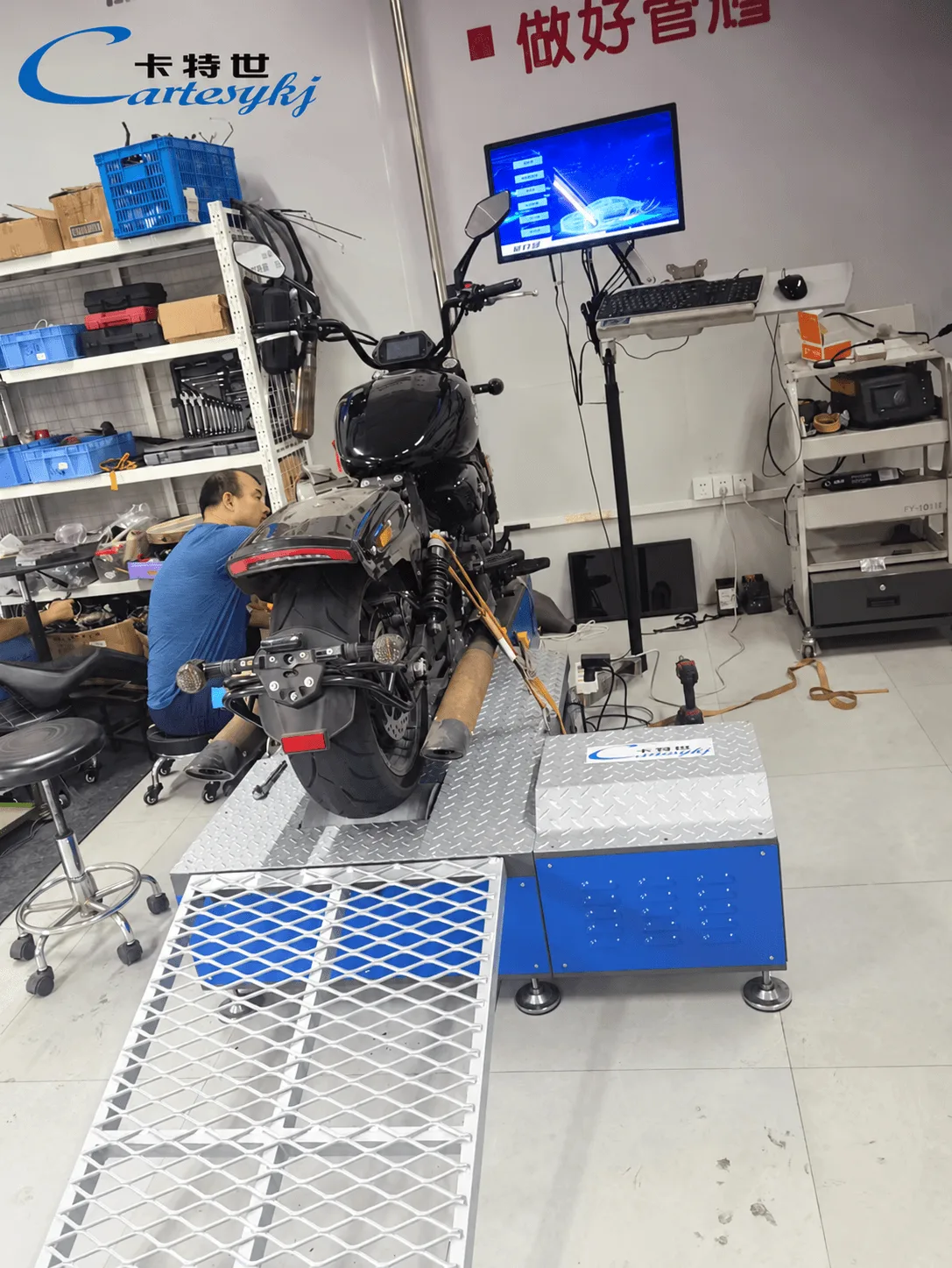
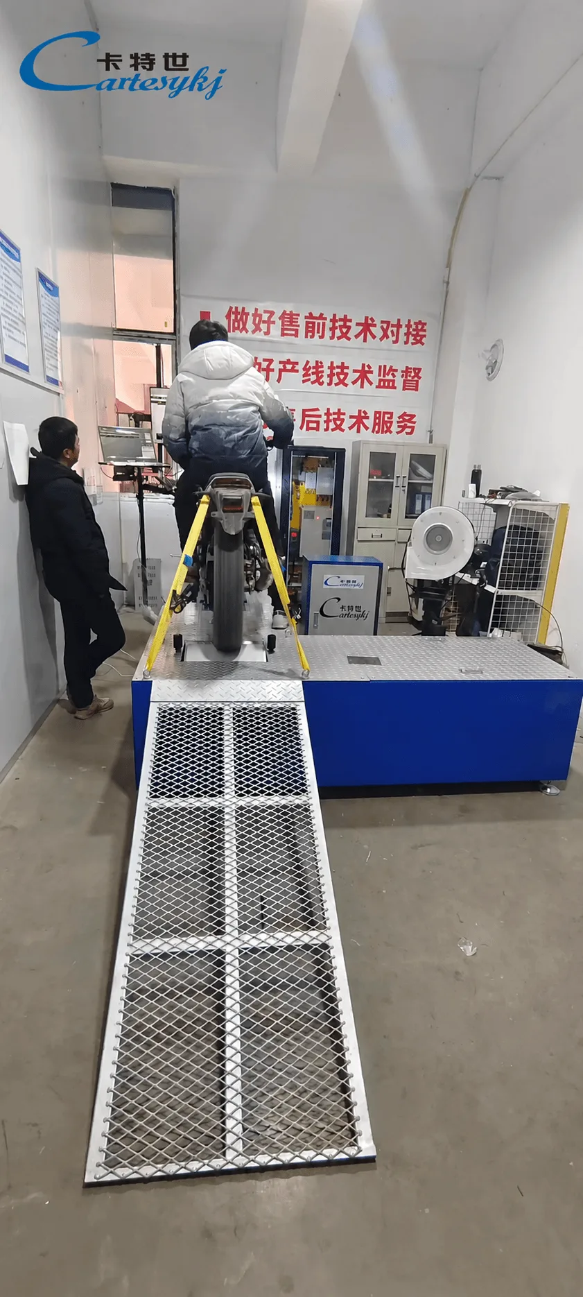
A motorcycle chassis dynamometer can provide the performance-testing function within an electric motorcycle testing solution. It evaluates defined performance at the driven wheel, while speedometer verification and horn.
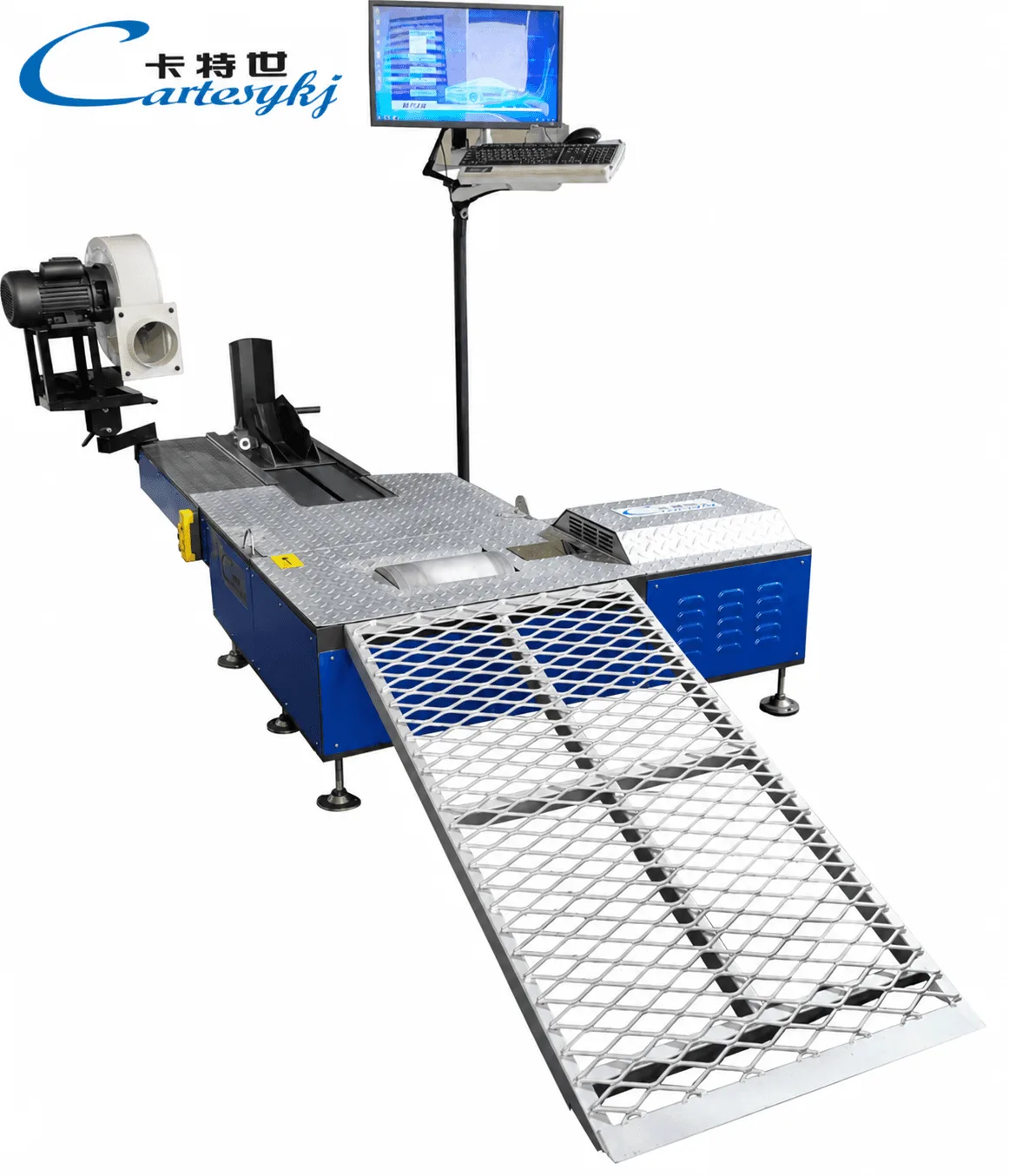
A motorcycle chassis dynamometer can provide the performance-testing function within an electric motorcycle testing solution. It evaluates defined performance at the driven wheel, while speedometer verification and horn sound-level testing address separate inspection questions.
Combining these functions requires more than connecting several instruments. Each test needs a documented method, suitable vehicle conditions, and a report that explains what the result represents. The equipment configuration should follow the intended electric motorcycles and the facility’s inspection or evaluation requirements.
For a U.S. facility, this means defining the test program before assigning equipment specifications or pass/fail limits. The following approach explains how dynamometer testing, speedometer checks, and horn measurements can fit into a coordinated solution.
What a Motorcycle Chassis Dynamometer Contributes
In a roller-based motorcycle chassis dynamometer, the driven tire transfers mechanical motion to a roller. Depending on the system’s design, the equipment measures or calculates performance quantities under the selected test conditions.
The configuration should identify which quantities are measured directly, which are calculated, and where the reported output is assessed. This distinction matters when interpreting power, torque, and speed data.
A wheel-power result describes output at the wheel according to the system’s documented method. It does not directly establish motor-shaft power or battery electrical input. Any estimate of motor output needs a defined calculation method and supporting assumptions.
Match the Dynamometer to the Required Test
The intended test determines which dynamometer functions are necessary.
A test that requires controlled resistance or a maintained operating point needs a configuration that supports those operating modes. Controlled loading, automated test sequences, and road-load simulation should be confirmed individually rather than assumed from the equipment name.
The technical proposal should connect each required test to the relevant measuring and control functions. It should also state the supported operating range and vehicle compatibility for the proposed configuration.
This provides a clear basis for deciding what the dynamometer can establish. A performance curve is useful when the report identifies the measured quantity, test method, and conditions behind it.
Keep Performance Results Within Their Scope
Mechanical output measurements alone do not establish battery health, usable battery capacity, or electrical insulation condition.
Similarly, a drivetrain-efficiency calculation requires defined input and output measurements. A wheel-power reading cannot, by itself, show how much electrical power the battery supplied.
Where the project includes electrical assessment, specify the additional instruments, measurement locations, and methods needed for that purpose. Those functions should appear explicitly in the solution rather than being implied by the presence of a dynamometer.
Define the Electric Motorcycle Test Conditions
Electric motorcycle testing needs a documented vehicle state so that results can be interpreted and compared appropriately.
The procedure should identify which conditions must be controlled and which must be recorded. Depending on the test, relevant information may include:
Battery state of charge.
Selected riding or operating mode.
Relevant battery or drive-system temperature information.
Tire configuration and conditions specified by the procedure.
Vehicle settings or software versions that affect the test.
The requirements should come from the selected method and vehicle documentation. A universal charge level, preparation time, or temperature range should not be assigned across different motorcycle models without supporting evidence.
For repeat measurements, the report should show whether the relevant conditions remained comparable. Otherwise, a difference between two results may be difficult to interpret.
Confirm Compatibility With Vehicle Controls
The proposed test procedure should account for the motorcycle’s drive configuration and control systems.
Where ABS, traction control, or another vehicle function affects roller operation, the relevant vehicle and equipment instructions should establish how testing is performed. Any required test mode must be supported by those instructions.
The manufacturer’s documentation should also cover positioning, support, and restraint for the intended motorcycles. These arrangements are part of the supported equipment setup and should not be inferred from platform dimensions alone.
Treat Regenerative-Deceleration Testing as a Separate Capability
If the motorcycle uses regenerative braking and the project includes its assessment, the dynamometer configuration and vehicle procedure must be expressly suitable for that purpose.
The ability to test propulsion performance does not establish the ability to conduct every deceleration test. The proposal should identify the required operating mode and the quantities the system can measure during that assessment.
It should also distinguish mechanical behavior at the wheel from electrical energy returned to the battery. Measuring the latter requires an appropriate electrical measurement method; it cannot be established from wheel-performance data alone.
Add a Motorcycle Speedometer Tester Where Verification Is Required
A motorcycle speedometer tester compares the motorcycle’s indicated speed with a documented reference-speed measurement under a defined procedure.
The comparison should identify the corresponding indicated and reference values at the specified test points. To interpret the result, the facility needs to know how the reference is established and what measurement capability supports it.
Vehicle compatibility is part of this assessment. The procedure should explain how the motorcycle produces its speed indication in the test arrangement and whether that arrangement supports the intended comparison.
Can the Dynamometer Also Perform Speedometer Checks?
A supplier may propose using a speed-measuring function within the dynamometer system. That approach needs documentation showing that the function and procedure are suitable for speedometer verification.
The presence of a roller-speed display alone does not establish a complete verification capability. The proposal should explain the relationship between the reference measurement and the motorcycle’s indicated speed, along with the relevant calibration and measurement information.
Where the same equipment supports both performance testing and speedometer verification, keep the results separately identified. A performance test and a speedometer comparison answer different questions, even when they share part of the hardware.
Include Motorcycle Horn Sound Level Testing as a Defined Acoustic Function
Motorcycle horn sound level testing assesses the horn’s acoustic output under specified measurement conditions.
A reported sound level needs context. Its interpretation depends on the instrument, microphone position, acoustic environment, and vehicle operating condition used during the test.
The procedure should therefore define
The sound-measuring instrument and its calibration requirements.
Microphone location, orientation, and measurement distance.
Relevant instrument settings.
Permitted background-sound conditions.
Vehicle and horn operating conditions.
The method used to record and interpret the result.
The selected test method should supply these requirements. Measurement distances, sound-level limits, or U.S. pass criteria should not be assigned without the applicable supporting procedure.
Plan the Acoustic Conditions Alongside the Mechanical Stations
A horn measurement needs an acoustic environment that supports the selected method. Sound from nearby equipment can affect the measurement, so the station plan should address the required background conditions.
If dynamometer testing and horn testing take place within the same facility, their layout and scheduling should account for those conditions. The method should determine whether separation by location, operating schedule, or another documented arrangement is appropriate.
Horn results can still appear in the same inspection report as dynamometer and speedometer results. Shared reporting does not require all measurements to take place at the same physical station.
A noise reading collected during dynamometer operation should not be labeled as a horn sound-level result. Each measurement must remain associated with the source and procedure it actually assesses.
Integrate the Tests Into a Two-Wheel Motorcycle Inspection Line
A two-wheel motorcycle inspection line should connect the required tests through a consistent vehicle record and documented workflow.
The line may combine several functions, but each should retain a clear purpose
| Test Function | Question It Addresses | Information Needed to Interpret the Result |
|---|---|---|
| Chassis dynamometer testing | What wheel-output performance is recorded under the selected test conditions? | Equipment configuration, measured and calculated quantities, vehicle state, and test method. |
| Speedometer verification | How does indicated speed compare with the reference measurement? | Reference method, comparison points, measurement capability, and applicable evaluation criteria. |
| Horn sound-level testing | What horn sound level is recorded under the specified acoustic conditions? | Instrument settings, microphone position, background conditions, and vehicle operating state. |
The workflow should begin by associating the motorcycle with the correct test program. Its identity should remain connected to all measurements and reports produced during that inspection.
The physical sequence should follow the documented procedures for the selected equipment and vehicle. Acoustic requirements, vehicle preparation, and any changes in operating state should be considered when arranging the sequence.
Specify How the Results Will Be Combined
When several instruments contribute to one report, define how their data will be transferred and associated with the motorcycle.
Automatic vehicle identification, direct instrument communication, shared databases, and report generation are functions to verify in the proposed system. Their availability should not be assumed because the equipment is supplied as one package.
The report should distinguish measured values, calculated outputs, and acceptance decisions. It should also make incomplete or omitted tests identifiable.
A sample report is a useful part of the technical proposal. It allows the facility to check whether the system preserves the units, conditions, and test information needed to understand each result.
Establish the Requirements for the U.S. Application
For a U.S. project, define the intended application before configuring acceptance limits.
The facility may be working to a named inspection program, a customer specification, or an internal evaluation procedure. The project documentation should identify the relevant electric motorcycle categories, test methods, reporting requirements, and acceptance criteria.
Keep the measurement record separate from the decision applied to it. The equipment records a result under stated conditions; the applicable rule determines how that result is classified.
A software-generated “pass” is meaningful only when the underlying rule is known and appropriate for the intended use. A general reference to a standard does not establish acceptance of a specific equipment configuration.
Where acceptance by a program administrator or another responsible body is required, establish the necessary evidence and process before relying on the installation for that purpose.
Turn the Test Program Into a Defined Equipment Solution
Provide the vehicle inspection equipment supplier with the intended electric motorcycle range, required measurements, reporting needs, and applicable project requirements.
Request a configuration proposal that explains how those requirements will be met. It should identify the dynamometer’s measurement and control functions, the speedometer-verification method, and any separate acoustic equipment required for horn testing.
The proposal should also include the supported vehicle configurations, installation requirements, calibration documentation, operating procedures, and a sample report. Where a demonstration is arranged, use an agreed motorcycle and procedure representative of the intended application.
An electric motorcycle testing solution is most useful when every result can be traced to a clear method and operating condition. A motorcycle chassis dynamometer supplies the defined performance-testing function; speedometer verification and horn sound-level testing add their own evidence. Connecting those functions through a documented workflow provides a practical basis for evaluating the complete inspection solution.
Project imagery